


- Copyrights, Trademarks, Registered Trademarks and Acknowledgements
- 1. Introduction
- 2. What's New
- 3. System Requirements and Installation
- 4. Getting Started
- 5. Data Fields and Properties
- 5.1. Data Field Properties
- 5.2. Common Data Field Properties
- 5.3. Data Fields That Appear Only When No Editable Item Selected
- 5.4. Text Frame
- 5.5. Barcode
- 5.6. Check Box
- 5.7. Image
- 5.8. Special Fields
- 5.9. Additional Formatting for Data Fields
- 5.10. Address Block
- 5.11. Paragraph Block
- 5.12. Table
- 5.13. PageNumber
- 5.14. Output Formats
- 5.15. PDF Forms
- 5.16. JavaScript For PDF Forms
- 6. Using the VisualXSL Application
- 6.1. How to Create a New Project
- 6.2. How to Create a Multi-Section Project
- 6.3. How to Add Data Fields
- 6.4. How to Fill In Preprinted Forms with Data
- 6.5. How to Use the Log Pane
- 6.6. How to Create PDF/PostScript Document with VisualXSL
- 6.7. How to Create Large Documents Faster by Using VDPMill Directly
- 6.8. How to Use the Command Line Interface
- 6.9. How to Add a Table Object
- 6.10. How to Edit a Field Pattern
- 6.11. How to Create Dynamic Templates
- 6.12. How to use JavaScript in PDF Forms
- 6.13. How to use Page Numbering
- 6.14. How to use Symbols
- 6.15. How to use Mvp.Xml EXSLT Module
- 7. Examples
- 7.1. Example of Creating XML Source and PDF Background
- 7.2. Example of Exporting XML Data File from SQL Server
- 7.3. Example of Using Radio Buttons
- 7.4. Example of Building a VisualXSL Project(W9 form)
- 7.5. Example of Building a VisualXSL Project (ICW form)
- 7.6. Example of Using XEP and SVG Files As Image
- 7.7. Example of Using Templates
- 7.8. Example of Using Custom Attributes
- 7.9. Example of Creating PDF Form
- Glossary
List of Figures
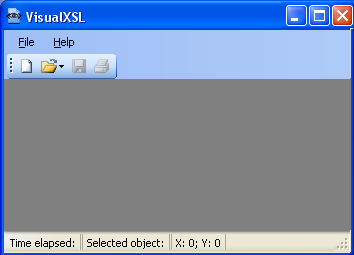
- 4.1. VisualXSL interface with no project opened
- 4.2. New Project dialog box
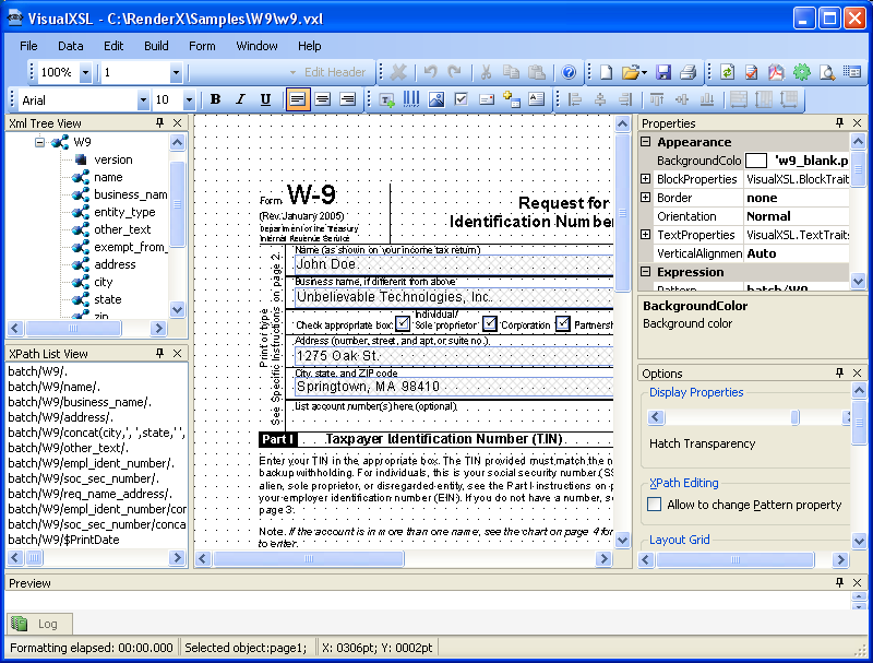
- 4.3. VisualXSL interface with the sample project opened
- 5.1. Address Block Wizard
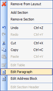
- 5.2. Selecting Edit Paragraph option in Address Block Wizard
- 5.3. Editing Paragraph in Address Block Wizard
- 5.4. Empty paragraph block added to the layout
- 5.5. Editing the paragraph block - some data fields and static text have been added
- 5.6. Choosing document format
- 6.1. Adding a new section to the project
- 6.2. Dragging XML node onto the layout
- 6.3. Warnings are blue in the log pane
- 7.1. Invitation letter
- 7.2. Data in the Excel spreadsheet
- 7.3. Warning that Microsoft Excel will create a schema based on selected XML file.
- 7.4. XML elements mapped to Microsoft Excel spreadsheet data columns
- 7.5. Letter with space left for employee personal data
- 7.6. Data in the Employees table
- 7.7. Query to export table data
- 7.8. Resulting XML file
- 7.9. Empty VisualXSL application
- 7.10. New Project wizard
- 7.11. New project page
- 7.12. Text formatting properties of the selected data field
- 7.13. View of unfinished project
- 7.14. Empty VisualXSL application
- 7.15. New Project wizard
- 7.16. Creating a Header
- 7.17. Dynamic document
- 7.18. Spaces between the items
- 7.19. Adding an Image
- 7.20. After Adding an Image and Selecting the ImageUrl Field
- 7.21. Edit ImageUrl dialog box
- 7.22. Lady_Red.xep has been selected for the new image
- 7.23. Diners (Credit Card) Statement file
- 7.24. CustomAttributes file, with table with cyan border
- 7.25. Preview, showing updated frame, with red left border, and blue top border
- 7.26. Registration Form
- 7.27. Registration Form
- 7.28. Registration Form
- 7.29. Registration Form
- 7.30. Registration Form
- 7.31. Registration Form
- 7.32. Registration Form
Copyrights, Trademarks, Registered Trademarks and Acknowledgements
RenderX is a registered trademark of RenderX Inc.
RenderX VisualXSL contains the following third-party software products:
-
Barcode components licensed from IDAutomation.com, Inc.
-
PDF2Image SDK libraries licensed from VeryPDF, Inc.
These products may be used only as part of and in connection with RenderX XEP and VisualXSL.
RenderX VisualXSL makes use of DockPanel Suite developed by Weifen Luo and licensed under the MIT License.
Certain components are based on part of the reusable wizard component developed by Steven M. Soloff.
iTextSharp is a C# port of the Java-based iText Library. iText is Copyright © 1999-2008 by Bruno Lowagie and Paulo Soares. All Rights Reserved. Read more about the iTextSharp library here: www.itextsharp.sourceforge.net (or www.sourceforge.net/projects/itextsharp/).
Adobe is a trademark and Acrobat Reader is a registered trademark of Adobe Systems, Inc.
Microsoft, .NET Framework, Microsoft Office, Microsoft Word, Microsoft Excel, Microsoft SQL Server 2000, and Windows Vista are registered trademarks of Microsoft Corporation.
1. Introduction
This manual describes how to work with the Visual XSL application.
1.1. Overview
VisualXSL is a GUI-based designer for writing eXtensible Stylesheet Language (XSL) stylesheets for use with RenderX XEP or XEPWin, and VDPMill. The product supports creating static overlay forms and flowing documents with variable page layouts based on position such as first, any, last and only. In fact, static and flowing documents can be mixed together into a complete XSL stylesheet project.
VisualXSL allows you to import a PDF or image as a background source or even start with a blank canvas. When using a background you can choose to render the form as part of the output (overlay) or render without the background for imaging on pre-printed stock. Simply associate a sample XML file with the project and then drag and drop XML data to design the document directly within the VisualXSL layout designer. Common properties like colors, fonts, borders and margins can easily be set with simple-to-use property sheets.
VisualXSL has wizards for many different types of document objects. Text fields, paragraphs with mixed static and dynamic content, tables, barcodes, checkboxes and variable images can all be created in the document layout from the XML source. Custom instructions, conditional rendering, date and number formats, and string conversions are all easy to add. VisualXSL is capable creating fillable pdf forms, including support of JavaScript.
The VisualXSL GUI supports the use of docking windows. You can dock and undock to create an optimal work configuration, with design in one window and preview in another. The design area supports pixel perfect placement to 1/100th of a point.
VisualXSL's architecture and functionality provides for a significant boost in speed of document production when compared to the traditional XSL-FO documents created with traditionally made XSL stylesheets.
Other features include:
-
Easy-To-Use Layout Designer
You design a document visually using VisualXSL. The application enables to put data fields onto the document layout. You can drag and drop data directly onto the layout designer.
The layout designer (also called the layout or the designer area) has a simple view, and is quickly and easily learned.
-
High-Speed Document Generation
VisualXSL generates a specific stylesheet for designed document rendering. With this stylesheet, the XEP formatter provides high speed document generation for PDF (or PostScript).
-
Single- and Multi-Page Forms Support
VisualXSL supports Single- and Multi-Page document creation.
If you set a multi-page PDF as a background, the application extracts every page of the background to the corresponding page of the resulting PDF. New pages are automatically added if needed.
-
Static and Dynamic flows
VisualXSL supports a mixture of static and dynamic templates.
-
Text Frames, Pictures, Barcodes, Paragraphs, Tables, Address blocks, Page numbers, Buttons, Check Boxes, List Boxes, and Combo Boxes.
The following types of data fields can be placed into a form:
-
Text Frames are rendered as text from the XML source file.
-
Check boxes are rendered as check marks (text symbol); their appearance (in the final document) depends on the XPath expression result.
-
Pictures are rendered according to the size set on the layout.
-
Barcodes are rendered using RenderX stylesheets and the data from the XML source file. The barcodes can be one of the following types:
-
EAN8
-
EAN13
-
UPC-A
-
UPC-E
-
Interleaved 2 of 5
-
Code 39
-
Codabar
-
Code 128
-
Australia Post 4-State
-
-
Paragraph blocks can be inserted and edited. They can be formed via XPath expressions, as well as from static text. You can also use different formatting for block text parts.
-
Tables can be inserted and edited. They can be formed via XPath expressions, as well as from static text (for certain cells). You can also use different formatting for different cells.
-
Address Blocks Wizard for adding address labels.The resulting label is aligned vertically to the bottom of the label and consists of four or five address lines. There are three areas in the wizard dialog.
-
Page Numbers are Paragraphs, which contain special texts, to show current page number in the document.
-
Buttons can be two types: Submit and Reset. The button's type is set via Button Type property. By default it is set Submit. All buttons have some common properties.
-
List Boxes and Combo Boxes are tools, which allows the user to select one or more values from the given list.
-
Multiselect - indicates, if multiple values can be selected
-
Values - list of selectable values, delimited by the given Separator. By default its value is the inner text of the XML node.
-
Separator- a symbol, indicating the separator for Values field by default its value is |. Also, ComboBox has one more property:
-
Editable - indicates if a value can be typed, or the value can only be selected from the given list
-
Note
Additional formatting can be applied to fields containing data values (in ODBC or ISO8601 format).
-
-
Conditional Rendering
Every data field has properties which can be set to determine its rendering under certain conditions.
-
XPath Validation
Almost all XPath expressions are created automatically when you drag and drop XML tree nodes onto the layout designer. You can also manually create or edit XPath expressions. The application validates all XPath expressions and offers to modify incorrect expressions.
-
Docking Windows
Docking-window interface is supported. You can dock and undock tool windows to create an optimal work configuration. For example, on a dual-monitor system, some tool windows can be undocked and placed on the second monitor.
-
Print XML Data on a Preprinted Form
Printing XML data over paper (preprinted) forms is supported. For more information, see section 6.4 How to Fill in Preprinted Forms with Data.
-
Generation of Fillable PDF Forms
The application can generate fillable PDF forms. For more information see section 5.15 PDF Forms.
-
EXSLT Support
The application is capable using EXSLT features provided with Mvp.Xml EXSLT.NET module (http://mvp-xml.sourceforge.net/exslt/). This module is not included in VisualXSL distribution and has to be installed separately.
1.2. Intended Audience and User Prerequisites
This manual is intended for personnel who need to generate PDF or PostScript documents from XML files.
To obtain maximum benefit from this manual and from the VisualXSL application, the user should have a basic understanding of XML, XSL, and XPath.
1.3. Document Content
This document contains the following:
1.4. Related Publications and References
1.5. Support
For all support-related needs, please go to www.renderx.com/support/index.html.
2. What's New
2.1. What's New in Version 2.4.2
-
Tables have no more border by default;
-
Fixed a problem with missing visual styles of checkboxes and radio buttons if they are used as Form fields;
-
Fixed wrong reference to base TranslateProject;
-
Fixed application crash when loading large documents;
-
Performance improved for loading and saving large documents;
-
Fixed application crash when loading large documents;
2.2. What's New in Version 2.4.1
2.3. What's New in Version 2.4
-
Added support for Mvp.Xml EXSLT.NET module (http://mvp-xml.sourceforge.net/exslt/), providing with EXSLT support;
-
Added support of document() XSLT function;
-
Resolved a problem with image Width attribute setting in dynamic layout;
-
Fixed several minor UI-related and logic problems;
2.4. What's New in Version 2.3.1
-
Fixed severe problems with JavaScript for radiobuttons and action buttons in PDF forms;
-
Further improvements and bugfixes over Undo;
-
Fixed a display problem after changing frame orientation under certain conditions;
-
Fixed a problem of Z-Order property when multiple blocks are selected;
-
Fixed an issue with incorrectly relocated Table and Address frames;
-
Fixed an exception if browser preview window is no longer accessible under certain conditions;
-
Fixed several issues with multiple inlines within paragraphs;
2.5. What's New in Version 2.3
-
Significant improvements over fillable PDF Forms. Now they are built with RenderX XEP and support most features from XEP, including fields, submit buttons, checkboxes, radiobuttons, and more;
-
Added feature of editing JavaScript event handlers for PDF Forms, associated with controls, pages, and documents;
-
Added support for different output formats, depending on those available in XEP license;
-
Major improvements over Paragraph editor (modifying and deleting fields, formatting and aligning the inlines);
-
Address Blocks now can be edited like normal paragraphs and have custom layout and additional fields within;
-
Improved Page Numbering widgets;
-
Improved moving frames with mouse and keyboard (Ctrl and Alt handling);
-
New samples and workflows in User Reference;
-
Fixed several problems with Table builder that prevented toolbar buttons working correctly;
-
Improved new and rotated items layout on a dynamic flow;
-
Temporary folder leakage (lost files) eliminated;
-
Several bugfixes with clipboard operations (Copy and Paste);
-
Fixed issues with traces on the layout;
-
Fixed critical error during Undo operation with paragraph and address blocks;
-
Fixed layout problems for very small frames;
-
Fixed an issue that prevented opening older versions of *.vxl files, and source files having CDATA elements;
-
Fixed problems with alignment, content deletion, and scaling within the paragraph editor;
-
Fixed several issues related to background image rendering;
-
Fixed a problem when tooltips remained on screen after the application was deactivated;
-
Improved logic of Inherit and Auto length values;
-
Fixed problems with incorrect image height in dynamic layout;
-
Minor bugfixes and code improvements;
2.6. What's New in Version 2.2
-
Major improvements over Table Builder; it is no longer an extra window but a regular control;
-
Improved visual appearance for text blocks in Design layout;
-
Added more examples in User's Guide;
-
Improved layout of the User's Guide (PDF and CHM versions);
-
Improved navigation (modal dialogs, keyboard shortcuts, etc);
-
Fixed issues with moving multiple objects;
-
Fixed clipboard issues;
-
Fixed issues with Undo/Redo;
-
Fixed issues with Drag-and-Drop operations;
-
Fixed several refresh issues with Property Grid;
-
Improved navigation (modal dialogs, keyboard shortcuts, etc);
-
Fixed update issues with installer;
-
Fixed several problems with popup menus;
2.7. What's New in Version 2.1
-
form is now a dockable pane.
-
is no longer shown when opening a previous project.
-
Added transparency control for brightness of hatch that is displayed for background of a data field.
-
Concept of 'add page' has been replaced by that of 'add section'.
-
Added support for mixed static and dynamic sections.
-
Added support for XEP intermediate format as an image.
-
Added support for SVG graphics as an image.
-
100% project translation customization, vastly extending the solutions possible with VisualXSL. For details, contact Support.
-
For the tech-savvy user, added custom attribute feature. There are three new properties, under the new Custom Properties group : CustomAttribute, Overridden Attribute, and CustomProcess. Using them, it is possible to add custom attributes (that is, attributes not yet natively supported by VisualXSL) to any object type.
-
New Document Wizard no longer appears at start up.
-
Other minor improvements have been added.
-
Fixed issue of application error when set to load last project on start up and that project is missing.
-
Other minor issues have been fixed.
2.8. Limitations
-
All project files, including the source XML file, should be located in the same folder.
-
To use the print of an address label capability with a PostNet barcode, you have to manually add a font data XML node to the configuration file (
XEP.xml). -
The PDF file name used as the background for the form layout must differ from the project name.
-
There is no validation for barcode values specified by XPath expressions. You should check manually whether the value is acceptable for a barcode. (XPath is validated, but there is no guarantee that the expression result will satisfy the barcode specification. For example, for UPC-A, the result of an expression should be a 12-digit number.)
-
A barcode image in the designer area is just a placeholder used to help locate the barcode data field. Only its height and location are taken into consideration. The width of the placeholder is ignored.
-
Currently, preview for PostScript files is not supported. Therefore, you cannot see the generated document if you choose the PostScript format. You can find the PostScript file by using the specified path.
-
The application considers the first node of the XML-file (source data) to represent its schema and to correspond to the record of the table described by this XML file. Note that this may cause problems with complex XML files whose first record structure is different from other nodes.
-
Any operation that directly or indirectly changes the section quantity cannot be undone.
-
All file paths to resources outside the project folder are stored as full paths. Be sure that all paths used in project are correct. Wherever possible, place all resources inside the project folder.
-
If you are working with several projects and a dialog window is opened for one of them, you cannot switch to another project. For example, when the window for a project is open, it is not possible to work with any other project.
-
An address block formed with the wizard and containing PostNet barcode cannot be edited.
-
Fillable forms are only applicable to PDF output format and will not work for other formats.
-
The VisualXSL application works with non-encrypted PDF only.
2.9. Known Issues
-
The list of known issues can be found in the Release Notes. See in ReadMe.txt file that is included in distribution package's Known Issues section.
3. System Requirements and Installation
3.1. Hardware/Software Requirements
The VisualXSL application requires the following hardware: 512 MB of RAM and 512 MB of free disk space.
Before installing the VisualXSL application, the following list of software must be installed:
-
Microsoft Windows 2000 SP4, Windows XP SP2, Vista or Windows 7,
-
Microsoft .NET Framework 2.0 or later
-
RenderX XEP formatter 4.17 or later
-
RenderX XEPWin 2.24 (part of the VisualXSL installation package; it is automatically installed)
-
Adobe Acrobat Reader 7.x. or later(or any web browser compatible PDF viewer, e.g.Foxit).
-
Microsoft Internet Explorer 5.5 or later
Recommended.
-
MS Office.
-
Some third party XML editor (for example oXygen XML editor).
-
Any PostScript viewer ( fore example Ghostscript v.8.64 and Ghostview v.4.9 , to have the ability to view prepared PostScript documents)
-
Windows AFP Viewer Plug-In ( to have the ability to view prepared AFP documents)
-
Adobe SVG Viewer ( to have the ability to view prepared SVG documents)
-
Microsoft XPS Viewer(to have the ability to view XPS documents, Microsoft .NET Framework 3.0 is required )
-
Mvp.Xml EXSLT.NET module for EXSLT support;
3.2. Product Package Folders
The installation folder (under C:\Program Files\RenderX\VisualXSL, if
the application's installation default folder is used) contains the following subfolders:
-
XSL - Contains the XSL stylesheets used internally by the application; it is not to be used separately from application.
-
Etc- Contains some data used internally. -
Doc- Contains the User Manual.
When the VisualXSL application is installed, the following new folder is created:
-
..\All Users\Shared Documents\VisualXSL Projects– shared documents folder for all users. If the application's installation default folder is used, theAll Usersfolder is underC:\Documents and Settings.Note
For Windows Vista and Windows 7 systems, the shared documents folder for all users is the following :
..\Users\Public\Public Documents\VisualXSL Projects
3.3. How to Install VisualXSL
The following procedure describes how to install VisualXSL.
-
Open the Control Panel
-
Add or Remove Programs, or Programs and Features
-
Find the VisualXSL application in the list of installed applications.
-
Click to Remove or Uninstall it.
Install a new version by executing the setup.exe and follow the wizard instructions. Note, that if you don’t have . NET Framework installed, wizard will try to download and install it from the Internet. If you fail to set the correct path to license.xml, you can copy this file to the application installation folder (by default: C:\Program Files\RenderX\VisualXSL on 32-bit Windows or C:\Program Files (x86)\RenderX\VisualXSL on 64-bit Windows).
- To enable TrueType Windows fonts the xep.xml (in XEPWin folder, for example C:\Program Files\RenderX\XEPWin \xep\xep.xml on 32-bit Windows or C:\Program Files (x86)\RenderX\XEPWin \xep\xep.xml on 64-bit Windows) file should be modified in the following way:
-
Make a backup copy of your xep.xml.
-
Open file in an XML Editor or WordPad, not NotePad, and find a string:
-
Click to Remove or Uninstall it.
Sample configuration for Windows TrueType fonts.
<!--
<font-group xml:base="file:/C:/Windows/Fonts/" label="Windows TrueType"
embed="true" subset="true">
<font-family name="Arial">
<font><font-data ttf="arial.ttf"/></font>
<font style="oblique"><font-data ttf="ariali.ttf"/></font>
<font weight="bold"><font-data ttf="arialbd.ttf"/></font>
<font weight="bold" style="oblique"><font-data ttf="arialbi.ttf"/></font>
</font-family>
...
</font-group>
-->
After modification it should look like:
Sample configuration for Windows TrueType fonts.
<font-group xml:base="file:/C:/Windows/Fonts/" label="Windows TrueType"
embed="true" subset="true">
<font-family name="Arial">
<font><font-data ttf="arial.ttf"/></font>
<font style="oblique"><font-data ttf="ariali.ttf"/></font>
<font weight="bold"><font-data ttf="arialbd.ttf"/></font>
<font weight="bold" style="oblique"><font-data ttf="arialbi.ttf"/></font>
</font-family>
...
</font-group>
See VisualXSL User Documentation for details, after the installation.
To uninstall VisualXSL :
-
Open the Control Panel
-
Add or Remove Programs (or Programs and Features for Vista and 7)
-
Find the VisualXSL application in the list of installed applications.
-
Click to Remove (or Uninstall) it.
-
If you also wish to uninstall RenderX XEPWin, use the Control Panel to uninstall this application
Procedure 3.1. To install VisualXSL:
-
After downloading the
visualxsl.zipfile, unzip it to a temporary folder.After unzipping, the folder contains the
setup.exe,Readme.txt, andWhatsNew.txtfiles. -
It is recommended to review both text files.
-
Go to the temporary folder and double-click
setup.exe.The Welcome screen for for VisualXSL opens.
-
Click .
The dialog box opens.
-
Select the option, and then click Next.
The dialog box opens.
-
Browsing to the license.xml file, specify its location and then click .
Note
During the installation, a copy of the
license.xmlfile is placed in the application installation folder (by default,C:\Program Files\RenderX\VisualXSL on 32-bit Windows or C:\Program Files(x86)\RenderX\VisualXSL on 64-bit Windows).The dialog box opens.
-
Fill in the and fields, select the option, and then click .
dialog box opens.
-
Select the setup type, and click .
Note
The setup is recommended only for experienced users.
dialog box opens.
-
Click .
Important
The installation starts.
The screen is displayed while VisualXSL is being installed.
-
Click to exit the
At the end of the VisualXSL installation, the VisualXSL icon is placed on the desktop.
Note
The following steps apply to a installation of XEPWin .
The screen of of XEPWin opens.
-
Click .
The dialog box opens.
-
Select the option, and then click .
The dialog box opens.
-
Browse to the
license.xml filespecify its location and then click . During the installation, a copy of thelicense.xmlfile is placed in the application installation folder (by default,C:\Program Files\RenderX\XEPWin\xep on 32-bit Windows or C:\Program Files (x86)\RenderX\XEPWin\xep on 64-bit Windows).The dialog box opens.
-
Fill in the and fields, select the option, and then click .
The dialog box opens.
-
Select the setup, and click .
The setup is recommended only for experienced users.
The dialog box opens.
-
Click .
Important
The installation starts.
The screen is displayed while XEPWin is being installed.
-
Click to exit the
At the end of the XEPWin installation, the Hot Folder icon is placed on the desktop and ActiXEP is placed on the taskbar.
Note
The following steps apply to an XEPWin Installation of XEPWin.
The screen of of XEPWin opens.
Note
To exit the
-
Click .
-
Click to confirm.
-
Click to exit the .
3.4. How to Uninstall VisualXSL
To uninstall VisualXSL, select Start > Control Panel > Add or Remove Programs, or Programs and Features > VisualXSL > Remove or Uninstall.
Note
If XEPWin is being used by another RenderX product, it should not be removed. If XEPWin is removed, the system must be restarted for the changes in XEPWin to take effect.
4. Getting Started
4.1. Opening the VisualXSL Application
Open the VisualXSL application by clicking its icon ![]() on the desktop.
on the desktop.
The application starts, with no project selected.
4.2. Opening an Existing VisualXSL Project
To open an existing project, do one of the following:
-
Click , and select the project that you want to open.
-
Click the
.VXLfile of the project that you want to open. -
Before closing VisualXSL, ensure that the Open last project on start toggle switch (located in the pane) is enabled (checked). When you launch VisualXSL next time, the last closed project will automatically be launched.
Note
Sample projects distributed with VisualXSL are located in :
For Windows 2000 and XP in: All Users\Shared
Documents\VisualXSL Projects\Samples folder.
For Windows Vista and 7 in: Users\Public\Public Documents\VisualXSL Projects\
Samples folder .
4.3. Creating a New VisualXSL Project
To create a new project:
-
If you want to create a new project from an existing project, the following should be done before continuing with the dialog box.
-
Create a new folder under
All Users\Document\VisualXSL Projects.
-
Place the data source (XML file) and, optionally, the background file (PDF or image) in this folder.
-
-
Click to open the dialog box and add a data source (the source XML).
(More information about preparing an XML source and PDF background is presented in later chapters.)

-
Use the dialog box to choose the project type that is applicable to your needs: or . Note that regardless of your choice, you can add both and templates to the project.
-
Optionally, use the field to add the background file (PDF or image). The background does not have to be added now; it can be added later.
-
In the dialog box, click the button. The folder and files to be used for the project are created, and the for VisualXSL opens.
Note
Click button to create blank project.
Click button to cancel new page addition
4.4. Main Window and Panes
The VisualXSL application has a docking style interface.
You can choose the windows from several predefined Main Window options from the menu: , , and . Also using the menu, you can toggle the appearance of individual panes: , , , , , and . The last window configuration used is saved when VisualXSL exits successfully and is restored on the next application startup.
Note
Because the panes are dockable, they can be detached from their position in the VisualXSL Main Window by double-clicking them and then moved to elsewhere on the monitor (even outside the VisualXSL Main Window) or to a second monitor (if you are using a dual-monitor system).
The combination displays the following panes:
-
XML Tree View, at the upper left, displays the XML schema.
-
XPath List View, at the lower left, displays a list of the XPath expressions.
-
Layout (Designer Area), in the upper middle of the screen, is the primary working area, where all data fields are placed according to the background form (only in sections).
-
Properties pane, at the upper right, displays the properties of the selected data field object in the properties grid. (Sometimes this pane is referred to as “object properties”.) You can select several objects at once by clicking them with the Ctrl button pressed. Only the common properties of the selected objects are displayed. If the values of the properties are the same they are displayed with the current value, otherwise they are shown as blank.
-
Options pane, at the lower right, shows miscellaneous options.
-
Preview pane, immediately below Layout, shows the PDF document preview.
-
Log pane, at the bottom of the screen, stores the formatter messages.
Note
Each of the panes above, except of Layout, has a (
 ) and a (
  ) button in its upper-right corner. You can
pin dockable windows via button. If a window is pinned, it
will always stay on the screen, otherwise it will be hidden as soon as it is not
focused.
) button in its upper-right corner. You can
pin dockable windows via button. If a window is pinned, it
will always stay on the screen, otherwise it will be hidden as soon as it is not
focused.
4.5. Menus
Most of the basic commands are placed on the menus for quick access. Almost all of them are also available in the toolbars.
-
File menu
The menu contains the following options:
-
New (Ctrl+N) - Opens a new project. Before opening a new project, you are prompted to save your changes to the current project.
-
Open Project (Ctrl+O) - Opens system's dialog, where you can select an existing project to open. Before opening a new project, you are prompted to save your changes to the current project.
-
Open Source XML (Ctrl+F) - Opens a system's dialog where you can select and add an XML data source to the project.
-
Save (Ctrl+S) - Saves the current project, with changes.
-
Save As (Ctrl+Shift+S) - Saves the current project, with changes, under a new name.
-
Print (Ctrl+P) - Prints the last generated PDF document. If you haven't created a resulting PDF or haven't previewed the result of XSLT, a warning message will be shown.
-
Recent Projects - Displays a list of recent projects.
-
Exit - Quits the VisualXSL application. You are prompted to save your changes.
-
-
Data Menu
The menu contains the following options:
-
Add Text Frame - Adds a text field to the layout, according to the XML source file. Current XML node's XPath expression is used to get the data from the XML source file. Note, that text frames can get static text as well as XPath.
-
Add Barcode - Adds a barcode field to the layout, according to the XML source file. Current XML node's XPath expression is used to get the data from the XML source file. Note, that barcodes can get static text as well as XPath (see detailed description in Barcode subchapter, in Data Fields and Properties chapter).
-
Add CheckBox - Adds a checkbox to the layout. The item's property (under group) can be specified to render the checkbox under only certain conditions. It must have the correct XPath expression in the context of the node set, as determined by the expression from property (see detailed description in Checkboxes subchapter, in Data Fields and Properties chapter).
-
Add Image - Adds an empty image field to the layout. Note: You must correct to generate images from the XML content. For example, to use the XML element content as the partial name for an image : property must be updated as the following :
concat('http://myintranet/images/', {xpath-value}, '.jpg')(see detailed description in Image subchapter, in Data Fields and Properties chapter). -
Add Address Block - Starts a wizard that adds an address label to the layout (see detailed description in Address Block subchapter, in Data Fields and Properties chapter).
-
Add Paragraph - Adds an empty paragraph data field to the design layout (see detailed description Paragraph Block, in Data Fields and Properties section).
-
Add Table - Adds a table to the layout (see detailed description Table, in Data Fields and Properties section).
-
Add Page Number - Adds a Page Number to the layout (see detailed description Page Number, in Data Fields and Properties section).
-
Add Button - Adds a Button to the layout (see detailed description Button, in Data Fields and Properties section).
-
Add List Box - Adds a List Box to the layout (see detailed description List Box, in Data Fields and Properties section).
-
Add Combo Box - Adds a Combo Box to the layout (see detailed description Combo Box, in Data Fields and Properties section).
-
-
Edit Menu
The Edit menu contains the following options:
-
Insert Symbol - Inserts symbols in your project.
-
Remove From Layout - Removes the selected data field(s) from the layout.
-
Add Section (Alt+P) - Adds a new section to the project.
-
Remove Section (Alt+R) - Removes the current section from the project.
-
Edit Section Header - Used only for dynamic sections. This option is for editing the static header of the current dynamic section.
-
Undo (Ctrl+Z) - Rolls back the last action.
-
Redo (Ctrl+Y) - Redoes the last undone action.
Note
For more information about and operations see Undo/Redo Operations subchapter.
-
Cut (Ctrl+X) - Removes and copies the selection to the clipboard.
-
Copy (Ctrl+C) - Copies the selection to the clipboard.
-
Paste (Ctrl+V) - Inserts the contents of the clipboard at the location of the cursor, and replaces any selected text or objects.
-
Edit Table - If a table data field is selected, that table's editor opens; if a table editor is opened, that editor closes; if no table is selected or multiple data fields are selected, this option is passive.
-
Edit Paragraph - If a paragraph data field is selected, that paragraph's editor opens; if a paragraph editor is opened, that editor closes; if no paragraph is selected or multiple data fields are selected, this option is passive.
-
Edit Address Block - If a address block data field is selected, that address block's editor opens; if a address block's editor is opened, that editor closes; if no address block's is selected or multiple data fields are selected, this option is passive.
-
-
Build Menu
The Build menu contains the following options:
-
Refresh - Refresh all data fields in the project.
-
Validate (F6) - checks all XPath expressions in all data fields in the project.
-
Generate XSL (F5) - Generates an XSL for the current project.
-
Preview (Ctrl+F5) - Generates preview for current project and shows it in the pane.
-
Create Resulting Document (Ctrl+Shift+F5) - Creates the resulting document from the current project.
-
Set Output Format - Set your desired output format from the current project.
-
PDF - .pdf output file
-
PostScript - .ps output file
-
AFP - .afp output file
-
XEP Intermediate - .xep output file
-
SVG - .svg output file
-
HTML - .html output file
-
XPS - .xps output file
-
-
Window Menu
The Windows menu contains the following options:
-
All Windows - Shows all windows. If this option is selected a check sign appears.
-
Optimized - , , , and panes are minimized. If this option is selected a check sign appears.
-
Lightweight - , , , , and panes are minimized. If this option is selected a check sign appears.
Note
Only one of the above mentioned options can be selected
Note
The last used window configuration is saved when VisualXSL exits, and is restored on the next application startup.
-
Reset Toolbars - Toggle set toolbars' deafult positions.
-
Preview - Toggle switch for showing/hiding the pane.
-
Log - Toggle switch for showing/hiding the pane.
-
Source XML - Toggle switch for showing/hiding the pane.
-
XPath List - Toggle switch for showing/hiding the pane.
-
Properties - Toggle switch for showing/hiding the pane. The pane is described in Data Fields and Properties chapter.
-
Options - Toggle switch for showing/hiding the pane. The pane is described at the end of this chapter.
-
List Open VisualXSL Projects. Lists all the VisualXSL projects that are open. The project that you are currently working on is checked. To work on a different project, click its name.
-
-
The Help menu contains the following options:
-
Contents (F1) - Opens VisualXSL User Guide.
-
- Lists general information about the application.
-
4.6. Toolbars
Most of the basic commands are placed on the toolbars for quick access. Almost all of them are also available in the menus.
-
-
 New Project - creates a new project.
 -
Open - is a drop-down list with the following options:
-
 Open Project - loads an existing project.
 -
 Open Source XML - opens and adds an XML data source to
the project.
Open Source XML - opens and adds an XML data source to
the project.
-
-
 Save - saves the current project with changes.
 -
 Print - Prints the last generated PDF document. If you
haven't created a resulting PDF or haven't previewed the result of XSLT, a warning
message will be shown.
Print - Prints the last generated PDF document. If you
haven't created a resulting PDF or haven't previewed the result of XSLT, a warning
message will be shown.
-
-
-
 Add Text Frame - Adds a text field to the layout, according
to the XML source file. Current XML node's XPath expression is used to get the data
from the XML source file. Note, that text frames can get static text as well as XPath.
Add Text Frame - Adds a text field to the layout, according
to the XML source file. Current XML node's XPath expression is used to get the data
from the XML source file. Note, that text frames can get static text as well as XPath.
-
 Add Barcode - Adds a barcode field to the layout, according
to the XML source file. Current XML node's XPath expression is used to get the data
from the XML source file. Note, that barcodes can get static text as well as XPath
(see detailed description in
Barcode subchapter, in
Data Fields and Properties
chapter).
Add Barcode - Adds a barcode field to the layout, according
to the XML source file. Current XML node's XPath expression is used to get the data
from the XML source file. Note, that barcodes can get static text as well as XPath
(see detailed description in
Barcode subchapter, in
Data Fields and Properties
chapter).
-
 Add Image - Adds an empty image field to the layout.
Note: You must correct
to generate images from the XML content. For
example, to use the XML element content as the partial name for an image :
property must be updated as the following :
Add Image - Adds an empty image field to the layout.
Note: You must correct
to generate images from the XML content. For
example, to use the XML element content as the partial name for an image :
property must be updated as the following :
concat('http://myintranet/Images/VisualXSL/', {xpath-value}, '.jpg')(see detailed description in Image subchapter, in Data Fields and Properties chapter). -
 Add CheckBox - Adds a checkbox to the layout. The item's
property (under group)
can be specified to render the checkbox under only certain conditions. It must have
the correct XPath expression in the context of the node set, as determined by the
expression from property (see detailed description in
Checkboxes
subchapter, in
Data Fields and Properties
chapter).
Add CheckBox - Adds a checkbox to the layout. The item's
property (under group)
can be specified to render the checkbox under only certain conditions. It must have
the correct XPath expression in the context of the node set, as determined by the
expression from property (see detailed description in
Checkboxes
subchapter, in
Data Fields and Properties
chapter).
-
 Add Address Block - Starts a wizard that adds an address
label to the layout (see detailed description in
Address Block
subchapter, in
Data Fields and Properties
chapter).
Add Address Block - Starts a wizard that adds an address
label to the layout (see detailed description in
Address Block
subchapter, in
Data Fields and Properties
chapter).
-
 Add Table - Adds a table to the layout (see detailed
description
Table, in
Data Fields and Properties
section).
Add Table - Adds a table to the layout (see detailed
description
Table, in
Data Fields and Properties
section).
-
 Add Paragraph - Adds an empty paragraph data field to the design
layout (see detailed description
Paragraph Block, in
Data Fields and Properties section).
Add Paragraph - Adds an empty paragraph data field to the design
layout (see detailed description
Paragraph Block, in
Data Fields and Properties section).
-
 Add Button - Adds a button to the design
layout (see detailed description
Button , in
Data Fields and Properties section).
Add Button - Adds a button to the design
layout (see detailed description
Button , in
Data Fields and Properties section).
-
 Add List Box - Adds a 'select box' to the design
layout (see detailed description
List Box , in
Data Fields and Properties section).
Add List Box - Adds a 'select box' to the design
layout (see detailed description
List Box , in
Data Fields and Properties section).
-
 Add Combo Box - Adds a 'combo box' to the design
layout (see detailed description
Combo Box , in
Data Fields and Properties section).
Add Combo Box - Adds a 'combo box' to the design
layout (see detailed description
Combo Box , in
Data Fields and Properties section).
-
-
-
 Remove From Layout (Del) - Removes the
selected data field(s) from the layout.
Remove From Layout (Del) - Removes the
selected data field(s) from the layout. -
 Undo
(Ctrl+Z) - Rolls back the last action.
Undo
(Ctrl+Z) - Rolls back the last action. -
 Redo (Ctrl+Y) - Redoes the last undone
action.
Redo (Ctrl+Y) - Redoes the last undone
action. Note
For more information about and operations see Undo/Redo Operations subchapter.
-
 Cut
(Ctrl+X) - Removes and copies the selection to the clipboard.
Cut
(Ctrl+X) - Removes and copies the selection to the clipboard. -
 Copy
(Ctrl+C) - Copies the selection to the clipboard.
Copy
(Ctrl+C) - Copies the selection to the clipboard. -
 Paste
(Ctrl+V) - Inserts the contents of the clipboard at the location of the cursor, and replaces any selected text or objects.
Paste
(Ctrl+V) - Inserts the contents of the clipboard at the location of the cursor, and replaces any selected text or objects. -
 Symbol
- Can include symbols in your project
Symbol
- Can include symbols in your project
-
-
-
 Refresh Design Layout calculates all XPath expressions and
refreshes the data fields content on the design layout (where possible).
Refresh Design Layout calculates all XPath expressions and
refreshes the data fields content on the design layout (where possible). -
 Validate Project checks all XPath expressions in all data
fields in the project.
Validate Project checks all XPath expressions in all data
fields in the project. -
 Create Resulting Document generates a document (PDF,
PostSript, AFP, XEP Intermediate, SVG, HTML or XPS) using all data records from the data source.
Create Resulting Document generates a document (PDF,
PostSript, AFP, XEP Intermediate, SVG, HTML or XPS) using all data records from the data source. -
 Generate XSL Stylesheet generates an XSL stylesheet for the
current layout. This stylesheet can be used with the RenderX XEP formatter to produce
PDF files.
Generate XSL Stylesheet generates an XSL stylesheet for the
current layout. This stylesheet can be used with the RenderX XEP formatter to produce
PDF files. -
 Preview Result of XSLT generates a PDF document preview,
using the specified number of data records.
Preview Result of XSLT generates a PDF document preview,
using the specified number of data records. -
 Create Local TranslateProject.xsl allows the customer to keep his/her own
TranslateProject.XSL in project directory.
Create Local TranslateProject.xsl allows the customer to keep his/her own
TranslateProject.XSL in project directory.
-
-
-
 aligns the selected data field to the left of the data field.
-
 aligns the selected data field to the center of the data field.
-
 aligns the selected data field to the right of the
data field.
aligns the selected data field to the right of the
data field. -
 aligns the selected data fields to the left side of
the first selected data field.
aligns the selected data fields to the left side of
the first selected data field. -
 aligns the selected data fields to the (horizontal)
center of the first selected data field.
aligns the selected data fields to the (horizontal)
center of the first selected data field. -
 aligns the selected data fields to the right side of
the first selected data field.
aligns the selected data fields to the right side of
the first selected data field. -
 aligns the selected data fields to the top of the
first selected data field.
aligns the selected data fields to the top of the
first selected data field. -
 aligns the selected data fields to the middle
(vertical center) of the first selected data field.
aligns the selected data fields to the middle
(vertical center) of the first selected data field. -
 aligns the selected data fields to the bottom of
the first selected data field.
aligns the selected data fields to the bottom of
the first selected data field. -
 makes selected data fields' widths the same as
the width of the first selected data field's.
makes selected data fields' widths the same as
the width of the first selected data field's. -
 makes the selected data fields' heights the same
as the height of the first selected data field's.
makes the selected data fields' heights the same
as the height of the first selected data field's. -
 makes the selected data fields' sizes the same as
the size of the first selected data field's.
makes the selected data fields' sizes the same as
the size of the first selected data field's.
-
-
-
 scales the layout.
 -
 switches the current section (available for
multi-section forms).
switches the current section (available for
multi-section forms). -
 opens the VisualXSL User Manual.
-
 selects the current template from the
list of available templates.
selects the current template from the
list of available templates. Note
The option is available only for a dynamic sections.
-
 is used to edit the static header of the current template.
Note
The option is available only for a dynamic sections.
-
 is used to change the font of the selected text.
-
 is used to change the font size of the selected text.
-
 is used to change the font of the selected text to/from bold.
-
 is used to change the font of the selected text to/from italic.
-
 is used to change the font of the selected text to/from underline.
-
4.7. Options Pane
The pane contains the following options:
-
-
Hatch Transparency is a slider for changing the transparency of the background. To make the background more transparent, move the slider to the left.
-
-
-
Allow changes to Pattern property specifies whether the Pattern property (under Expression, in the Properties pane) may be changed. This allows the user to deviate from the supposed/default page pattern.
-
-
-
Snap to Grid switches on/off data fields' align to the grid in the layout designer area.
Note
Snap to grid is used only for static sections.
-
Grid Size sets the size of the grid cell in pixels.
Note
Is active only if is switched on. The minimum allowed size is 4 pixels and the maximum allowed sized is 60 pixels.
-
Draw Grid switches on/off the grid draw.
Note
If the grid size is too small for the selected scale, the grid will not be displayed.
-
-
-
Number of records to preview enables you to limit the number of records used to generate the preview. It can be useful when the source XML contains a large number of records.
-
Open last project on start switches on/off the automatic opening of the last project at the application's next start.
-
Render form background switches on/off the generation of the form background.
Note
Only the Number of records to preview and Render form background options will take an effect immediately; the other options require application restart.
-
-
-
File Format is the raster format of the image file.
-
Color Depth is the number of bits per pixel in an image format used to rasterize the form background.
-
Rasterized resolution (in DPI) specifies the horizontal and vertical resolution of the rasterized image of the form background.
-
4.8. Undo/Redo Operations
Most actions that are made in and panes can be rolled back using the Undo and Redo commands. Note the following points regarding changes, actions, and operations:
-
All changes made to a data field object while it is still selected are considered to be one action, therefore Undo/Redo treats them as a single action. For example, if both the size and position are changed while the same data field is selected, will roll back both changes. However, if the size is changed for one data field and the position for a second data field, will roll back the last action only.
Note
In VisualXSL and operations are multistep operations. It means that you can roll back and forward the last operations multiple times.
-
Operations to add or remove sections cannot be undone.
The selected data fields, or a selected whole section, can be copied to the Clipboard, and then pasted one or more times to the same or another window of the application (if more than one project is being edited at the same time).
Important
Make sure that newly pasted data field has the correct XPath expression. To do this, either select , or press F6, or click the toolbar button.
5. Data Fields and Properties
5.1. Data Field Properties
This chapter describes the data properties (in the pane) associated with the various field types that can be added to a VisualXSL project from the menu. The properties are grouped according to ,, , ,, , , , , , and , as described in this chapter.
Important
If a data field has been selected, the change you make to a property affects only that field.
When no data field has been selected, the change in formatting for a property affects all data fields on the section that use the template's formatting for that property. However, a data field which property (for example, font size) has been set individually, is not affected by the change of template formatting for that property.
Note
Many of the fields in the panel have drop-down
lists,  buttons, etc. that appear only
when the data field is selected in the panel.
buttons, etc. that appear only
when the data field is selected in the panel.
5.2. Common Data Field Properties
The following data fields, which appear in alphabetical order under pane, are used for all data fields.
-
specifies the color for the background. For example, choosing white makes the area behind the data field white in the resulting PDF.
-
is a subgroup that contains the following properties:
-
specifies the text alignment. The possible values are:
-
Inherit
-
Left
-
Center
-
Right
-
Justify
-
-
AlignmentLast specifies the text alignment for the last line of the text block. It has the same set of values as Alignment.
-
LineFeed corresponds to the XSL-FO linefeed-treatment property, which defines how line feed characters are handled. The possible values are :
-
Inherit sets this property to the value of the parent container.
-
TreatAsSpace forces the formatter to treat line feed characters as a space.
-
Ignore lets the formatter ignore any line feed characters.
-
Preserve treats all line feed characters as line breaks.
-
TreatAsZeroWidthSpace forces the formatter to treat line feed characters as a zero-width space.
Note
displaying this feature in the designer area is not implemented.
-
-
WrapOption specifies whether the text should be wrapped to fit the data field's frame.
-
-
is a subgroup that is used for specifying the border properties:
-
BorderColor specifies the border color.
-
BorderStyle specifies the border line style.
-
BorderWidth specifies the line width.
-
-
is the block orientation which can be used for rotating data fields. This property corresponds to the XSL-FO reference-orientation trait.
-
the texts contains the vertical alignment. The possible values are :
-
Auto sets vertical alignment to the default value (Before) or to the value of the parent container.
-
Before sets vertical alignment to the top of the data field.
-
Center sets vertical alignment to the center of the data field.
-
After sets vertical alignment to the bottom of the data field.
-
-
contains the Z-Order.
The use of the following custom properties requires knowledge in XSL-FO and XSLT.
-
is a space-delimited list of new XSL-FO styles.
-
is used to pass a trigger into the TranslateProject.xsl where a user can then override the typical template used to process that element. This allows complete customization for any frame type in the drawing grid.
-
specifies the XSL-FO style(s) to omit.
-
is used to generate comments in the resulting stylesheet. It is a description for the field. Besides, it can be helpful for navigating the document structure.
-
specifies the line style of the border.
-
specifies the field name.
-
specifies the field value.
-
is the XPath expression that selects an XML branch (node set) used for the data field.
Caution
If you manually modify the XPath expression in the property, be sure that it is correct and evaluates to an XML node set, and that this node set is a descendant of the XML node evaluated with the section property. It is suggested to validate your project to make sure all XPath expressions are correct.
-
contains the XPath expression that defines the conditions for showing or hiding the content.
-
contains two logical values: true/false. If true, field will not be shown on the layout
-
which has deafult ' 0 ' value. The maximum allowed count of the entered symbols
-
contains two logical values: true/false. If true the text field may contain more than one fields
-
contains automatic generated value. Required unique property for all fillable fields.
-
contains two logical values: true/false. If true
-
contains two logical values: true/false. If true the text field is generated as a password field: instead of symbols,
*are shown -
contains two logical values: true/false. If true, the field can be printed
-
contains two logical values: true/false. If true, no data can be inserted
-
contains two logical values: true/false. If true, some data is required to be entered
-
contains two logical values: true/false. Is editable only for and , as for all other fillable fields it is set true and is Readonly.
-
contains the first-line indentation for the data field. It corresponds to the XSL-FO trait
text-indent. -
contains the last-line indentation for the data field. It corresponds to the XSL-FO trait
last-line-end-indent. -
contains the left indentation for the data field. It corresponds to the XSL-FO traits
start-indent. -
contains the right indentation for the data field. It corresponds to the XSL-FO traits
end-indent.
-
can write some javascript code to invoke, when the cursor leaves the field
-
This event is defined when a change in a form requires that all fields that have a calculation script attached to them be executed. All fields that depend on the value of the changed field will now be recalculated.
-
can write some javascript code to invoke, when a field loses or receives focus.
-
can write some javascript code to invoke, when format is wrong.
-
This event occurs whenever a user types a keystroke into a text box or combo box (including cut and paste operations) or selects an item in a combo box list or list box field. A keystroke script may limit the type of keys allowed. For example, a numeric field might only allow numeric characters.
-
can write some javascript code to invoke, when a mouse button is pressed down in the field area.
-
can write some javascript code to invoke, when a mouse pointer enters in the field area.
-
can write some javascript code to invoke, when a mouse pointer exits in the field area.
-
can write some javascript code to invoke, when a mouse is pressed up in the field area.
-
can write some javascript code to invoke, when when validate.
-
contains the padding of the text from the data field's frame's bottom border, in points.
-
contains the padding of the text from the data field's frame's left border, in points.
-
contains the padding of the text from the data field's frame's right border, in points.
-
contains the padding of the text from the data field's frame's top border, in points.
-
contains the height of the data field's frame. The value for Height can use the following units of measurement:
-
points (pt)
-
pixels (px)
-
inches (in)
-
centimeters (cm)
-
millimeters (mm)
Note
If no unit of measurement is specified, the default (points) is used.
-
-
contains the width of the data field's frame. The value for the property can use the same measurements as for the Height property.
-
contains the height of the space after the area of the data field's frame, in the specified units. The measurements of and properties are used, the default value is
pt. -
contains the height of the space before the area of the data type, in the specified units. The measurements of and properties are used, the default value is
pt.
5.3. Data Fields That Appear Only When No Editable Item Selected
The following data fields appear only when there is no editable item selected.
-
-
can write some javascript code(e.g. some alert) to invoke after printing the document.
-
can write some javascript code(e.g. some alert) to invoke after saving the document.
-
User can write his/her own JavaScript library for the document and use in at any desired place.
-
can write some javascript code(e.g. some alert) to invoke, when the document is opened.
-
can write some javascript code(e.g. some alert) to invoke, before closing the document.
-
can write some javascript code(e.g. some alert) to invoke, before printing the document.
-
-
-
specifies the path to the background (PDF or image file) that is used.
-
displays type of current section,
Truefor dynamic sections,Falsefor static sections. -
specifies the path to the rasterized copy of background image file that has been initially specified in property.
-
-
-
displays whether the section is dynamic
Trueor staticFalse. Read only.
-
5.4. Text Frame
Besides the properties mentioned in Common Data Field Properties, the following additional properties are used for Text Frames:
-
is a subgroup that contains properties for formatting text inside the data field:
-
Font is a subgroup that specifies the text's font properties.
-
Name specifies the font type. You can set font type via both typing the font type name into the box and choosing the font type from the drop-down list.
-
Size specifies the font size. The measurement unit is specified by .
-
Unit specifies the unit for . It is one of the following:
-
Pixel - the measures in pixels.
-
Point - the Size measures is points.
-
Inch - the Size measures in inches.
-
Millimeter - the Size measures in millimeters.
-
-
Bold specifies whether the font is bold-faced.
-
Italic specifies whether the font is italicized.
-
Strikeout specifies whether the font has a strike-out line through it.
-
Underline specifies whether the font is underlined.
-
-
ForeColor specifies the text color (the foreground color).
-
-
-
is a custom data format description.
-
contains XSLT code that defines additional field formatting. For more details, see section Additional Formatting for Data Fields , where there is also a table of available codes.
Note
The application does not provide the list of codes and does not check their validity. If an incorrect value is set for this property, the default code (
0) is used in the resulting XSL. -
specifies the data type stored in the XML source. This property provides information that is necessary for formatting the text from the XML source. Currently, only the Date and Text types are supported.
-
is a design-time text to be displayed at the layout. It has special meaning for some fields. For more information see below, at Image and at Special Fields.
-
-
-
is an XPath expression that returns a value from a node set defined in the property.
-
5.5. Barcode
Besides the properties mentioned in Common Data Field Properties, the following additional properties are used for barcodes:
-
-
Module is the width of the narrowest stripe in the barcode, in one of the following measures:
-
pixels (px)
-
points (pt)
-
inches (in)
-
centimeters (cm)
-
millimeters (mm)
Note
The default measure is pixels (px)
Use this parameter to control the width and height of the barcode.
-
-
-
-
Type is the barcode type. Available barcode types are:
-
EAN8
-
EAN13
-
UPC-A
-
UPC-E
-
Interleaved 2 of 5
-
Code 39
-
Codabar
-
Code 128
-
Australia Post 4-State
Note
No validation of an XPath expression result to the barcode specification rules is available.
-
-
5.6. Check Box
Besides the properties mentioned in Common Data Field Properties, the following additional properties are used for check boxes:
-
-
CheckType specifies the style of the check mark. The possible values are:
-
Default
-
Check
-
LightCheck
-
LightCross
-
Cross
-
LightWavyCross
-
WavyCross
-
Plus
-
EmptyPlus
-
Bullet
-
EmptyBullet
-
Square
-
EmptySquare
-
-
specifies the font size of the check mark inside the field.
-
-
-
BorderStyle specifies the style of the check box's border. The possible values are:
-
None
-
Solid
-
Beveled
-
Dashed
-
Inset
-
Underline
-
-
CheckStyle specifies the style of the check box. The possible values are:
-
None
-
Check
-
Circle
-
Cross
-
Diamond
-
Square
-
Star
-
-
FieldName specifies
-
Value specifies
-
5.7. Image
Besides the properties mentioned in Common Data Field Properties, the following additional properties are used for images:
-
-
ImageUrl is the URL or the local path to the image file. By default it is a static path to the image. To change it, click the
button, which opens the file browse
dialog. If you want to use to extract a part of the URI from XML,
use the tag {xpath-value} inside the property.Note
XPathValue, in Expression, by default is not used for a newly created field. To extract the image URI from the source XML using XPath, you should manually edit the property. For more details, see the following example.
-
Example
Suppose we have employees' photos that are stored in a shared folder of our intranet server. All files are named in the following way:
http://intranet-server.com/photo/XXXX.jpg, where XXXX is a serial number from 1 to 9999.Suppose that we also have the following XML fragment describing every employee:
<employees> <record id="1"> <name>John Doe</name> </record> <record id="2"> <name>Adam Smith</name> </record> </employees>We should use the following values to render images in our document:
Property Value ImageUrl http://intranet-server.com/photo/{xpath-value}.jpg XPathValue @id Pattern records/record
-
-
5.8. Special Fields
You can insert special fields into the project. When generating the XSL stylesheet, the special fields are transformed into XSL parameters. This feature enables you to set some values at the XSL transformation stage.
Special fields are described in the format-plugin.xml (it is created
in the ProgramFiles/RenderX/VisualXSL/XSL folder). To insert a special
field, drag and drop its XML node from the XML tree view onto the layout. Change the value of
the XPathValue property of the created object's properties to the name of the desired field
(see the following list). The name should be specified with the preceding symbol
$.
| Field Name | Description | Default Value |
| PrintDate | Date when the project was last transformed | Current date |
| CreateDate | Date when the project was created | None |
| AuthorName | Name of the project author | None |
| CompanyName | Name of the author’s company | None |
You can also insert a custom special field, which is later transformed into a stylesheet
parameter. Set the property to
$<special-name>, where special-name is CName (it
satisfies standard XSL rules of naming variables). Set the default value of the parameter by
changing the property.
5.9 Additional Formatting for Data Fields
Data field contents can be customized by additional formatting. Currently, only different date formats are implemented:
-
ISO8601 format (
yyyy-mm-ddThh:mm:ss:mmm) -
ODBC canonical format (
yyyy-mm-dd hh:mi:ss)
Note
The date value in source XML file should be properly specified in one of the implemented formats.
Select the field containing the correct date value for formatting application. Switch to its object properties, and choose Date value for the property. Then specify the format code for the property. All supported format codes are listed in the table below. To refresh the designer area (and see the updated formatting of the data field), click the button.
| Code | Description | |
| without century | with century | |
| 1 | 101 | USA mm/dd/yy |
| 2 | 102 | ANSI yy.mm.dd |
| 3 | 103 | British/French dd/mm/yy |
| 4 | 104 | German dd.mm.yy |
| 5 | 105 | Italian dd-mm-yy |
| 6 | 106 | dd mon yy |
| 7 | 107 | Mon dd, yy |
| 8 | 108 | hh:mm:ss |
| 9 or 109 | Default + milliseconds mon dd yyyy hh:mi:ss:mmmAM (or PM) | |
| 10 | 110 | USA mm-dd-yy |
| 11 | 111 | JAPAN yy/mm/dd |
| 12 | 112 | ISO yymmdd |
| 13 or 113 | Europe default + milliseconds dd mon yyyy hh:mm:ss:mmm(24h) | |
| 14 | 114 | - hh:mi:ss:mmm(24h) |
| 20 or 120 | ODBC canonical yyyy-mm-dd hh:mi:ss(24h) | |
| 21 or 121 | ODBC canonical (with milliseconds) yyyy-mm-dd hh:mi:ss.mmm(24h) | |
| - | 126 | ISO8601 yyyy-mm-ddThh:mm:ss:mmm(no spaces) |
Note
Milliseconds (if they are specified in the XML data for the field) are not rendered after the layout is refreshed, but are rendered in the resulting PDF document.
5.10. Address Block
The application provides for adding address labels. The resulting label is aligned vertically to the bottom of the label and consists of four or five address lines. There are three areas in the wizard dialog (see the following figure). The first area, at the left of the dialog, is a tree representing the first element of the XML source file (only the first batch of the XML source is visible in the ). The second area, at the upper-right of the dialog, is a group of textboxes for the parts of the address. The third area, at the lower-right of the dialog, is a preview for the address label. You can add data from the XML tree to text boxes by double-clicking on the tree node, by dragging nodes into the , or by clicking the button.
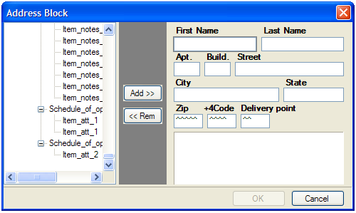
If you click the button, data is added to the highlighted text box. If you add new data to a text box that already contains some data, the new data replaces the old data. To clear the highlighted text box, click the button. The data is added from the XML tree in such a way that it is dynamically inserted into the resulting document. Besides, you can type some static data if you need it.
The application forms the PostNet barcode from the three last text boxes (ZipCode, +4Code, Delivery Point). It assumes that all data typed into them are numeric, so make sure that the XML data represents a proper number for a post code.
Address blocks are generated as a special kind of Paragraph Block. This means that they can be edited as both Paragraph and as Address. Editing as Address allows you to visually modify address-related fields, while editing as Paragraph provides with assigning fonts, colors, and customizing order and layout of address fields. The application has possibility for both ways of editing Address blocks.
Double-clicking on Address Frame invokes Address editor to allow changing Address fields.
Procedure 5.1. To invoke Paragraph editor on Address block
-
Create an Address block using the Wizard
-
Close the Wizard to save your initial changes
-
Right-click the Address block on layout
-
Select pop-up menu item (see Figure 5.2)
-
-
The paragraph editor will open the content of the Address block (see Figure 5.3).
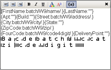
The fields of wizard block are specified in curl brackets. Before semicolon symbol “:” there is name of field, after that symbol there is content of that filed. To set special font setting, it is important to select the content of filed and from toolbar set the appropriate formatting. It is impossible to see the formatting options while you are editing the address block in wizard. For font options visualization you could press toggle view button “{a}” which is located on paragraph toolbar and could see the view of address label which will be in resulting document.
Note
Currently, the application has no option for specifying the fonts to be used in document formatting. Therefore, to describe the PostNet True Type font, you should manually edit the configuration file for XEP and add a section as shown in the following example.
Procedure 5.2. To manually edit the configuration file:
Assume that XEPWin is installed in the C:\Program
Files\RenderX\XEPWin folder.
-
Open the
XEP.xmlfile fromxepsubfolder. -
Find the
font-groupXML element with@label="Windows TrueType"attribute. -
Add the following text inside the found element:
<font-family name="IDAutomationPOSTNET" embed="true"> <font> <font-data ttf="IDAutomationPOSTNET.ttf"/> </font> </font-family>This enables the for the XEP formatter to use True Type font to render PostNet barcodes.
5.11. Paragraph Block
You can put paragraphs with different formatting properties into one block container, or paragraph block. An example of such a paragraph block is an address block. Using a paragraph block allows you to prepare text blocks using XML data of variable length.
Note
You cannot leave any data field blank, but at least one block must be filled.
Using a paragraph block also helps when you wish to apply different formatting to different parts of one paragraph.
Initially, when you add a paragraph block to the project (from the menu), it has one paragraph. The content of the block is rendered from the selected XML node. You should select from the menu or double-click on the Paragraph block in order to add a new paragraph, or to edit existing ones inside the block. This brings up the following view:
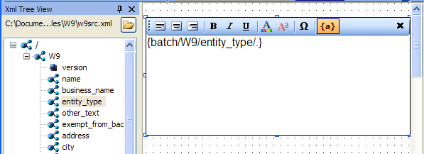
You can type static text into the paragraph block, drag and drop nodes with data from the XML tree, or type an
XPath expression inside curly brackets ({}). To apply formatting to the text,
select it, and then click the appropriate toolbar button.
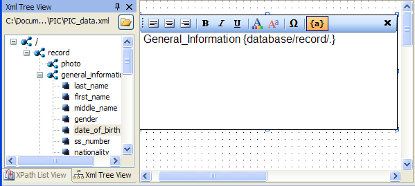
To finish editing the paragraph, select , or click the button.
Caution
Before editing a paragraph block, ensure that the entire block on the (the ) is visible to you. In some cases, you must scroll the manually to see all text being edited.
Note
undo/redo is not supported while editing the paragraph block.
5.12. Table
The following additional data field is used for tables.
-
-
RepeaterPattern is the context with which the table data will repeat.
For example, if you have XML as
root/customersand there are many/customerelements below/customers, the Table XPath expression would beroot/customersand the table RepeaterPattern would beroot/customers/customer.
-
5.13. PageNumber
Page Number is a Paragraph, which contains a special text, to show current page number in the document.
By default, Page Number is in Page ' i ' of count format, where ' i ' is the current page's number and count is the count of the pages in the document.
5.14. Output Formats
You can get following with VisualXSL :
-
-Portable Document Format
-
- PostScript
-
- Advanced Function Printing
-
-
- Scalable Vector Graphics
-
- Hyper Text Markup Language
-
- XML Paper Specification
Note
To be able to use those you need:
-
a license file allowing to use
-
a separate license file allowing to use (because of Formatter behaves differently seeing AFP backend in the license file - namely, disabling kerning and some other features)
Procedure 5.3. Creating Output formats
Note
The default of VisualXSL is
-
To choose the output format for the document,select from menu or click the
Set Output Formatbutton: <;/p>
.
-
From the drop-down list, select either or . ( is not Supported yet).
Note
For more information about see RenderX XEP
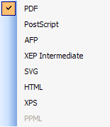
5.15. PDF Forms
VisualXSL 2.3 and later versions provide a new way of creating fillable Acrobat® forms. From now on VisualXSL uses XEP to create fillable forms, which made this process fast and simple. The process of creating fillable forms fully differs from the processes used in previews versions. First, creating fillable form is not a separate process, furthermore, the fillable fields are created like any other field; the only difference is property in the pane. If is set to true, in the resulting PDF the field will be a created as a fillable field, otherwise the field will be a normal PDF field.
Important
Forms are only applicable to PDF output format and will not work for other formats.
Important
In order to create fillable Forms, XEP requires a special
license. The license file should be put in xep folder in the
XEPWin installation folder.
Note
In the 2.3 version VisualXSL supports as fillable fields only Text Frames, CheckBoxes, RadioButtons, Buttons, ListBoxes and ComboBoxes. Other frames cannot be created as fillable form fields. Each frame is described above at this section.
Note
It is no longer required to set PDF background in order to create fillable forms.
All the frames which can be made fillable PDF fields have several common properties. You can set/view them at the pane.
-
- is editable only for and , as for all other fillable fields it is set true and is Readonly.
-
- required unique property for all fillable fields. By default VisualXSL generates a unique name for all fields, but you can change property for fillable fields.
Note
Be sure NOT to have multiple fillable fields with the same . Otherwise, fields will not be generated normally.
-
- if true, no data can be inserted
-
- if true, some data is required to be entered
-
- if true,
-
- if true, field will not be shown on the layout
-
- if true, the field can be printed
Besides the common properties has some specific properties.
-
- the default text entered into the field
-
- if true the text field may contain more than one field
-
- if true the text field is generated as a password field: instead of symbols,
*are shown -
- the maximum allowed count of the entered symbols
Besides the common properties has some specific properties.
-
- required property to indicate separate Radio Buttons groups. All the radio buttons with the same are in one radio group. VisualXSL defaults a unique for Radio Buttons, but you can set your own names.
-
- indicates if the field is initially selected
-
RadioButtons are generated as series of CheckBoxes. You just need to
-
Create several CheckBoxes
-
In the properties of each CheckBox give the same left part (e.g. if there are several conditions that compare certain expression with different constant values)</p>
-
Set the CheckBoxes' properties to true
-
Generate the resulting PDF document
See Example of Using Radio Buttons for an example of generating Radio Buttons.
-
VisualXSL 2.3 supports two types of buttons : Submit and Reset. The button's type is set via property. By default it is set Submit
All buttons have some common properties.
-
- space delimited list of affected field names. If empty string is given, all fields are included. The default value is empty string.
-
- Text shown on the button
is used for submitting form data to the server. Besides the common properties, it contains some others:
-
- Required, the server URL, to which the data will be sent. By default its value is the inner text of the XML node.
-
- Possible values are : XFDF, FDF, PDF, HTML. The default value is XFDF
-
- Possible values are : POST and GET. The default value is POST
Both and are tools, which allows the user to select one or more values from the given list.
-
- indicates, if multiple values can be selected
-
- list of selectable values, delimited by the given . By default its value is the inner text of the XML node.
-
- a symbol, indicating the separator for field by default its value is |.
Also, has one more property:
-
- indicates if a value can be typed, or the value can only be selected from the given list
Procedure 5.4. To create a fillable Acrobat® form
Assume you already have some frames on your document and now want to add some fillable ones.
-
Add the frames you wish to make fillable (e.g. Text Frames, CheckBoxes and RadioButtons)
-
Select those frames, which will be fillable fields and navigate to pane.
-
Change the properties value to true (by default it is set to false).
-
Create resulting PDF file
5.16. JavaScript For PDF Forms
VisualXSL 2.3 and later versions support JavaScript for PDF forms. You can write JavaScript code for fillable PDF fields, for pages and for the PDF document, also you can write your JavaScript library for the PDF document. For fillable fields JavaScript is written in properties in the pane.
All the fillable fields (Text Frames, Checkboxes, Radio Buttons, Buttons, Listboxes, ComboBoxes) support JavaScript events. Bellow is the list of supported events.
-
- invokes when the cursor leaves the field
-
- This event is defined when a change in a form requires that all fields that have a calculation script attached to them be executed. All fields that depend on the value of the changed field will now be recalculated.
-
- invokes when a field loses or receives focus.
-
- invokes when format is wrong.
-
- This event occurs whenever a user types a keystroke into a text box or combo box (including cut and paste operations) or selects an item in a combo box list or list box field. A keystroke script may limit the type of keys allowed. For example, a numeric field might only allow numeric characters.
-
- invokes when a mouse button is pressed down in the field area.
-
- invokes when a mouse pointer enters in the field area.
-
- invokes when a mouse pointer exits in the field area.
-
- invokes when a mouse is pressed up in the field area.
-
- invokes when validate.
VisualXSL 2.3 supports two JavaScript events for pages. Which can be found among properties in the pane.
-
- invokes when new page is opened.
-
- invokes when window is closed.
These are hooks for events of a page coming into or out of the view in the PDF reader.
They go transparently to <xep:page> and then to Page objects in
PDF document for each page created with the page master where the attributes were
set.
VisualXSL 2.3 supports several JavaScript events for the document. Which can be found among properties in the pane.
-
- invokes when the document is opened.
-
- invokes after printing the document.
-
- invokes after saving the document.
-
- invokes before closing the document.
-
- invokes before printing the document.
VisualXSL 2.3 also allows the user to write his/her own JavaScript library for the document and use in at any desired place. The library is written in the property under property group in the pane.
Procedure 5.7. To create a PDF file with JavaScript for the document
-
Create Project
-
Select the layout and navigate to pane.
-
Write
function f() { app.alert("function f() is called"); }JavaScript code at property -
Write
f();JavaScript code into the property -
Create resulting PDF file
-
Open the created PDF file. See the "function f() is called" message.
6. Using the VisualXSL Application
6.1. How to Create a New Project
Procedure 6.1. To create a new project:
-
Run a project in VisualXSL with one of the above-mentioned methods.
-
If the previous project loaded automatically on startup, press the button on the toolbar, or select the menu item, or press the Ctrl+N key combination.
-
To select the XML file (it must be a well-formed XML document), either use the File | Open Source XML menu item, or press the Ctrl+F key combination. After the XML file is successfully loaded, its schema is shown in the .
-
To set the required properties in , click an empty space of the section in Layout and do as follows:
-
Specify the Pattern property in the property grid. The property should contain a valid XPath of an XML element.
Note
The XPath expression is case sensitive.
-
Set the BackgroundPath property value to the valid full path of the previously prepared PDF file (which contains the form that you want to fill with data from the XML). It can easily be done by clicking the
button.
-
You can also set an alternative value for the RasterizedPath property. Set it to the valid full path of a previously prepared raster file with a form you want to fill with data from the XML.
Note
Currently, the application supports the following raster image formats: PNG, TIFF, JPG, and GIF (for more details, see the RenderX XEP On-line Reference).
-
6.2. How to Create a Multi-Section Project
Procedure 6.2. To create a multi-section project:
-
Create a new project (see How to Create a New Project above).
-
Select an XML file either by using the File | Open Source XML menu item or by pressing Ctrl+F.
-
In the object properties, set the BackgroundPath property to a full path of the required multi-page PDF.
You can click the
button to use the
open file dialog. After the PDF background is selected, the first section is rendered in
the layout area and the full path to the rasterized version appears in the object
properties in the
RasterizedPath
property. Also, the application creates a PDF for every section of the selected PDF, and
produces rasterized versions of them. Rasterized files are generated
from the multi-page PDF background file. For each page a separate PDF and PNG files
are generated. Files are created in the project folder and named:
PDF File-NameXXXX.pdfandPDF File-NameXXXX.png, whereXXXXis a section number starting from 0001. These files are set as the backgrounds for the corresponding pages.
If you do not have a PDF file with a form, but you have a file in a supported graphics format such as PNG, TIFF, JPG, and GIF (for more details, see RenderX XEP On-line Reference), you may manually set its path to the property.
-
Add and adjust the data fields for this section (see, How to Add Data Fields below).
-
When all data fields have been added and are properly adjusted, click the toolbar drop-down list with the active section number (see the figure 6.1 above).
The drop-down list shows the currently available section numbers, and at the bottom of the drop-down list there is a New Page item. Click this item if you need to add a new section to the project. Alternatively, you can use the Edit | Add section menu item or press the Alt+P key combination. To add a new section, you may also enter the next number of the last section's number.
-
To remove the currently selected section, use the Edit | Remove section menu command or the Alt+R key combination.
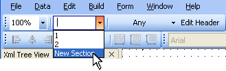
6.3. How to Add Data Fields
After the project is created, you can add, modify, or remove data fields.
Data field is a frame on the . It is dynamically rendered in the resulting document by getting data from the XML data file.
Procedure 6.3. To add a new data field:
-
Select a node in the . The data stored in this node is rendered in the resulting form.
-
Click the toolbar button to add a field with the selected XML node to the design layout. Alternatively, you can drag a selected tree node and drop it onto the layout. A new data field appears in the form layout. Or, you can drag an item by holding the right mouse button. In that case, after releasing the mouse button in the desired place on the layout, you can choose a data field type from the context menu.
-
You can now select the newly added frame by clicking it, and setting its desired position by dragging it over the layout.
-
A data field, when selected, has handles at the corners and at the middle of the sides. You change the location and size of the data field by dragging.
-
Additional properties can be modified for a selected data field in the .
After all data fields are added and aligned, you can generate the XSL stylesheet and/or the resulting PDF document.
During the PDF rendering, fields are filled with data from the XML file. See the detailed properties description in the Data Fields and Properties chapter.
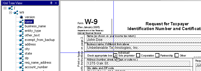
6.4. How to Fill In Preprinted Forms with Data
Procedure 6.4. To fill in preprinted forms with data fields:
-
Create a new project in VisualXSL.
-
Scan to a raster image of the preprinted form and set it as the background, or use an existing PDF.
-
Add data fields and all necessary pages.
-
Using pane, clear the Render form background check box.
-
Save the .VXL file.
-
Generate your PDF with the data fields only, and print it on your preprinted form(s).
Note
To restore the background rendering in the destination document, check the check box when you are finished.
6.5. How to Use the Log Pane
The traces the progress of the formatting. It contains all the messages from the XEP formatting engine. The messages are highlighted in the following way:
-
Errors – red;
-
Warnings – blue;
-
Other - black.
Some messages contain clickable links (warnings and errors related to incorrect XPath expressions in data fields). You can click those messages to go to the problematic data field.
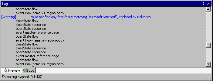
It is recommended to look at the log after every document formatting. If the document is not generated successfully, the log can show the reason why.
6.6. How to Create PDF/PostScript Document with VisualXSL
After a project is created and all necessary data fields are placed on the layout, you can create a PDF or a PostScript document.
Procedure 6.5. To create a PDF/PostScript document:
-
Set Output Format
toolbar icon or use the menu command and select output format.
A File Save dialog box appears.
-
Click the toolbar icon or use the menu command .
A File Save dialog box appears.
-
Type in the file name for your document, set the desired document format (PDF or PostScript), and click .
Note
The application automatically rasterizes PDFs into an image when PostScript files are generated and a PDF file is set as the background for the project. This raster image is used as the background in the document.
Generation of the document can take some time, depending on the number of pages and the PDF background form's complexity.
Note
If your XML file contains a large number of records, you may get Not enough memory to format error. To fix this issue, increase Java memory settings (
-Xmsand–Xmxkeys) forCliser Service(a part of XEPWin package used by VisualXSL). For details see the CliserService.exe.config. file installed in the assumed location ofC:\Program Files\ RenderX\XEPWin folder.However, if the number of pages is more than this setting can handle, see below How to Create Large Documents Faster by Using RenderX VDPMil for the solution.
6.7. How to Create Large Documents Faster by Using VDPMill Directly
Creating documents with VisualXSL is acceptable if you need only to generate a small number of pages of a simple form (1-100 pages). However if you need to generate thousands of pages of a document, it is much faster to use RenderX VDPMill directly.
VDPMill is a complete solution with very high performance rendering of both large print files as well as singular large reports.
VDPMill can generate very large batch print files – hundreds of thousands of pages in a single file. Through the use of a multi-threaded formatting grid for documents, the components of this print file can be formatted simultaneously to meet any performance demands. The Formatter layer administrative tools allow the user to add/remove server connections from the grid so all that is required to increase performance is to add additional RenderX XEP server threads. The Formatter automatically balances the load across the new server threads. The Customizer is fully extendible, allowing the user to modify the print stream as desired before generation of output. This eliminates the need for custom PDF, PostScript and AFP parsers or concatenations. And using the multi-threaded Generator, VDPMill can produce simultaneous output documents from the same internal document stream, eliminating the need and inherent deficiencies of trying to convert one output format to another. For example, the user can produce one large batch of invoices as a PostScript or AFP file for print and selected invoices in that batch as PDF or PDF Form for electronic presentment or e-mail.
VDPMill is the perfect application for all your high performance print and large report production, and dynamic and interactive PDF Forms.
6.8. How to Use the Command Line Interface
VisualXSL has a command line interface that gives access to the application functionality from the Windows console.
The syntax to use is:
VisualXSL.exe <VisualXSLProject.vxl> <SourceXml.xml>
<ResultingFile.pdf | ResultingFile.ps>[options]
where
-
<VisualXSLProject.vxl>is the full path to a VisualXSL application previously designed project file. -
<SourceXml.xml>is the full path to the source XML file containing data to be used in the transformation. -
<ResultingFile.pdf | ResultingFile.ps>is the full path to the resulting PDF or PostScript file name.Note
If the path contains spaces, it should be enclosed with double quotes.
The [options] is one of the followings:
-
-?- displays a message box with the command line syntax help.
-
-l<FULLPATH>- sets the log file name to store messages of the formatting process, where<FULLPATH>is a file name with the full path.
-
-r<NUMBER>– sets the number of the records to be extracted from the XML file to perform generation of the document, where<NUMBER>equals the expected number of records.
Example:
The following command line shows the feature in action:
VisualXSL.exe "%ALLUSERSPROFILE%\Documents\VisualXSL
Projects\Samples\W9\W9.vxl" "%ALLUSERSPROFILE%\Documents\VisualXSL
Projects\Samples\W9src.xml" "%ALLUSERSPROFILE%\Documents\VisualXSL
Projects\Samples\W9\W9.pdf" –l"%ALLUSERSPROFILE%\Documents\VisualXSL
Projects\Samples\W9\W9.log" –r5
Note
%ALLUSERSPROFILE% is a Windows system variable that
contains the path to the user's Documents folder.
This example uses the W9.vxl sample project file
with only first five records from W9src.xml to produce
W9.pdf, in the ..\ All
Users\Documents\VisualXSL Project\Samples\W9\ folder, and log
all the events to W9.log file located in the same
folder.
Note
In Windows Explorer "Documents" folder may be shown as "Shared Documents".
6.9. How to Add a Table Object
You can add a table object either by using the menu command or by clicking the toolbar icon or right click on XML tree view and select .
To edit a table double-click on it. You can also select it and click the menu command or right-click the table and for the context menu click the command. The opens and toolbar is added, where you can perform the following actions:
-
 Add a table column.
-
 Add a table row.
-
 Delete a table column.
-
 Delete a table row.
-
 Delete the content of a cell.
-
 Add or delete a table header.
-
 Add or delete a table footer.
For more detailed information about these actions see Table section.
A table, when selected, has handles at the corners and at the middle of the sides. You change the location and size of a table by dragging.
In the pane, you can set the properties of a table, such as:
-
-
Appearance
-
Border
-
BorderColor
-
-
-
Appearance
-
Border
-
BorderStyle
-
-
-
Appearance
-
Border
-
BorderWidth
-
For more detailed information about Table Builder see Table section.
6.10. How to Edit a Field Pattern
To see if editing a field pattern is currently enabled, look in the pane's property. If this field is disabled, the field pattern editing is not currently enabled.
To enable the field pattern editing, go to the pane's and select the check box. The field is now available.
For example, let's concatenate the first name field and the last name field to produce the full name.
Assume that the parent node is parent_name. Assume that the two name fields are:
first_name, last_name. Then the XPath expression will be:
concat(parent_name/first_name, ' ', parent_name/last_name)
6.11. How to Create Dynamic Templates
VisualXSL supports a mixture of static and dynamic templates. Dynamic templates can be created in any project, whether it was defined as Dynamic Document (in the dialog box) or as a .
The default template in a dynamic document is the Any template.
To create additional templates for the project, click the button. From the drop-down list, select either Only, First, Last, or Any. If the template does not exist, it is created. This template is the current template for the project. That is, this button can also be used to select the current template.
Note
For more information, see the Extensible Stylesheet Language (XSL) web site, under the "page-position" paragraph.
VisualXSL knows how many sections are in the project and assigns the templates according to the following rules.
For a single-section dynamic document, the Only template is used if it exists, otherwise the Any template is used.
For a multi-section dynamic document:
-
The First template is used for the first section if this template exists, otherwise the Any template is used.
-
The Last template is used for the last section if this template exists, otherwise the Any template is used.
-
If there are any intermediate sections (that is, other than the first and the last sections), the Any template is used.
6.12. How to use JavaScript in PDF Forms
VisualXSL 2.3 and higher support JavaScript for PDF Forms. There are three types of JavaScripts for a document: JavaScript for a frame, JavaScript for a page and JavaScript for the hole document.
Procedure 6.6. To write JavaScript for a frame
-
Open/Create a VisualXSL project
-
Add a
-
Navigate to pane and set property to True
Note
JavaScript can be written only for those fields, which property is True.
-
Navigate to property in the section of the pane. Use
 icon to open
VisualXSL's JavaScript window. Usually it is used to paste
(Ctrl + V) the JavaScript written in a JavaScript
editor, but this is a simple example and we can write our JavaScript code into the
opened window:
icon to open
VisualXSL's JavaScript window. Usually it is used to paste
(Ctrl + V) the JavaScript written in a JavaScript
editor, but this is a simple example and we can write our JavaScript code into the
opened window: app.alert("Mouse entered the field", 2); -
Generate resulting document or preview results (PDF)
-
Open the generated PDF document
-
Move the mouse cursor to the field. Mouse entered the field message is shown.
6.13. How to use Page Numbering
VisualXL 2.3 and higher versions contain a new field - Page number. Page Number is a Paragraph, which contains a special text, to show current page number in the document.
Procedure 6.7. To add a Page Number
-
Open/Create a new VisualXSL project
-
Click icon on the Toolbar menu or Data | Add Page Number menu item
-
Create resulting document and see page number on each page of the document
Note
By default, Page Number is in
Page i of countformat, where i is the current page's number and count is the count of the pages in the document.
6.14. How to use Symbols
VisualXSL 2.3 and higher contain a new feature, you can include symbols in your project.
Procedure 6.8. To use Symbol
-
Open/create a VisualXSL project
-
Add a frame
-
Click
 icon on
. window
opens.
icon on
. window
opens. -
Choose the symbols by double-clicking on them or via button
-
Click button and close the window
-
Open the paragraph and paste (Ctrl + V) the selected symbols.
Note
You can use (paste) the copied symbols for any allowed frame.
6.15. How to Use Mvp.Xml EXSLT Module
By default, VisualXSL is using native .NET libraries (MSXML) for XSL transformations during Preview and Generate Document operations. However, this library does not support EXSLT by its own. In order to employ EXSLT features for resulting documents, VisualXSL is capable using alternative library, Mvp.Xml Project: EXSLT.NET module.
Mvp.Xml is is a community-developed implementation of the EXSLT extensions to the XSLT 1.0 for the .NET platform. You can download it from its Web site, (http://mvp-xml.sourceforge.net/exslt/. After downloading, just unzip the binaries to VisualXSL folder.
No additional steps required. VisualXSL is looking for Mvsp.Xml.dll in its folder (same as the VisualXSL.exe is located) and if found, uses it via reflection.
7. Examples
7.1. Example of Creating XML Source and PDF Background
For this example Microsoft Office Professional Edition 2003 (or later) must be installed.
You can use Microsoft Excel to prepare an XML source file and Microsoft Word to make an invitation letter form.
In this example, you prepare and mail an anniversary party invitations to all company managers named CEO. All employees’ information is stored in an Excel spreadsheet (see Figure 7.1 below). The letter should look like the one in the figure below, and you should be able to print it or Email it as an electronic document.
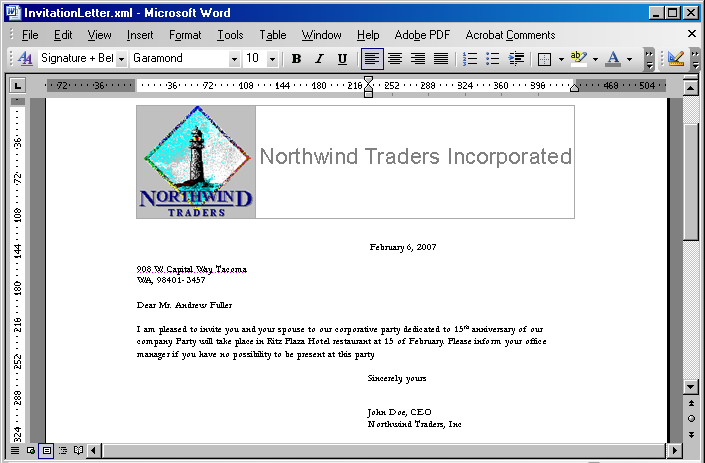
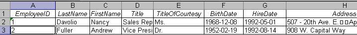
First of all, create the XML source file. You should have an XML schema to be able to map the data to the XML tags and export it to an XML file. The simplest way to do that is to prepare a small XML file describing the common structure of your data.
The XML file should look like the following example (you can omit any elements not necessary for your task). You should write the XML node corresponding to the data record twice to make Microsoft Excel realize that this node can be replicated many times.
Attach a new XML map by doing the following:
-
Open the tab by selecting .
-
Click the button, which opens the window with the XML map list.
-
Add a new file by clicking the button and selecting a prepared XML file as an XML source.
-
When a warning message appears saying that no XML schema is referred to this file, click .
Excel creates the schema automatically.
-
Map all XML elements to the spreadsheet data columns, you can see the instructions in the bottom of the tab. After you have finished, you can export the spreadsheet to XML.
-
Save your spreadsheet as an XML file to your project folder.
-
To prepare a PDF document that can be used as a background, you can use Microsoft Word and create a document with space left for variable data. The document might look like the following Figure 7.5. Save it as an XML (WordML) file.
-
Use XEP Assistant and WordML2FO stylesheets from the XEPWin package to produce a PDF file from your mockup.
With the XML source file and the PDF file, you have the files necessary for creating a new project.
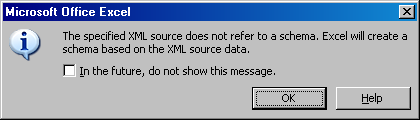
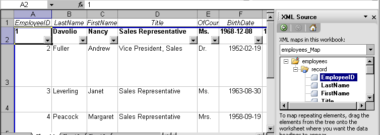
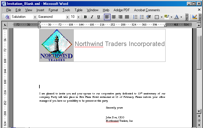
7.2. Example of Exporting XML Data File from SQL Server
For this example we use the Northwind test database and Query Analyzer (Microsoft SQL Server 2000) for the data conversion.
-
Open SQL Query Analyzer(Microsoft SQL Server 2000).
-
Connect to the Northwind database.
Our goal is to convert data from the Employees table.
-
Assume that the file with the converted data should be placed under
c:\temp\. -
Using any text editor (for example Notepad), create the
template.tplconversion template file in this folder. -
Use the editor to enter the following in this template file:
<root> <%begindetail%> <%insert_data_here%> <%enddetail%> </root> -
Enter the following query into the SQL Query Analyzer window (see the following figure)
EXEC sp_makewebtask @outputfile = 'c:\temp\myxmlfile.xml', @query = 'select * from Employees for xml auto', @templatefile = 'c:\temp\template.tpl'
where:
-
@outputfile- the full path to file XML. -
@query– the sql query for the necessary data. -
@templatefile- a file template to use for creating the XML file.
-
-
Run the query by pressing F5 or by selecting from the menu.
The
myxmlfile.xmlfile is created in thec:\temp\folder. -
The Employees table data is exported to XML format.
-
Continue to next sample to build a VisualXSL document.
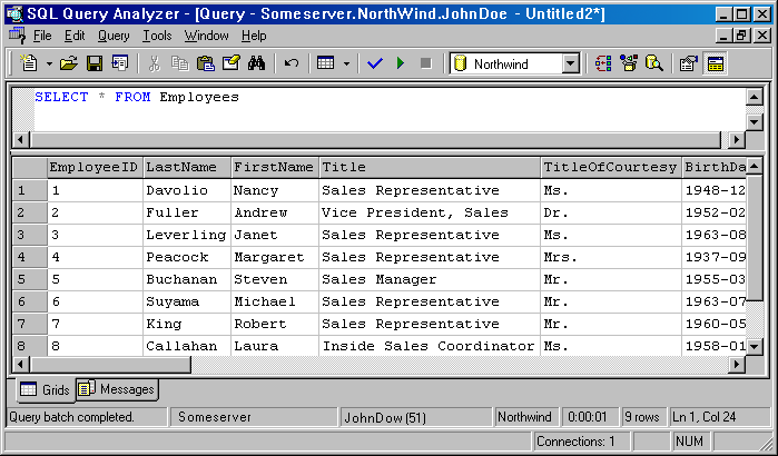
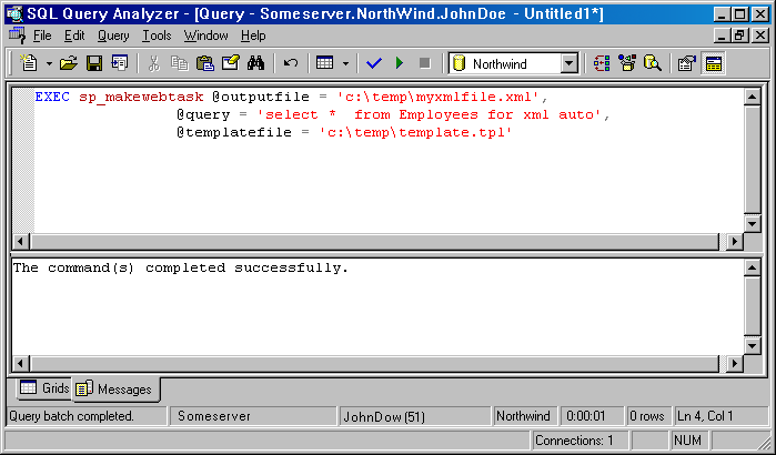
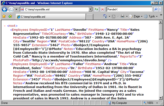
7.3. Example of Using Radio Buttons
When creating fillable PDF forms, you may need to be able to add radio buttons in your form. Unlike check boxes, radio buttons are grouped so that only one of them can be selected at a time. Creating radio buttons in VisualXSL is similar to creating checkboxes; the only difference is that the Test property of these elements must have the same variable name in their XPath expressions (but different values to compare with). Another way to create is to give the same for all .
Note
Radio Buttons are created only if their Treat as Field property is set true.
This example assumes you are starting from an existing project. To start a new project, see Creating a New VisualXSL Project and How to Create a New Project.
Prepare a number of reports in W9 form from existing data (in the C:\Documents
and Settings\All Users\Documents\VisualXSL Projects\W9 folder. A sample PDF file
with a W9 form (for the background) and an XML file from the database already exist.) For
information about preparing an XML source and PDF background, see Example of Creating XML Source and PDF
Background and Example
of Exporting XML Data File from SQL Server.
7.4. Example of Building a VisualXSL Project(W9 form)
This example assumes you are starting from an existing project. To start a new project, see Creating a New VisualXSL Project and How to Create a New Project.
The example covers the design and publishing of documents based on the US Government W9 form from existing data in the
..\All Users\Shared Documents\VisualXSL Projects\samples\W9 folder
or
..\Users\Public\Public Documents\VisualXSL Projects\Samples\W9 folder.
A sample PDF file with a W9 form (for the background) and an XML file from the database already exist. For information about preparing an XML source and PDF background, see Example of Creating XML Source and PDF Background and in Example of Exporting XML Data File from SQL Server.
Procedure 7.1. To build a VisualXSL project
-
Create a new folder in
C:\Documents and Settings\All Users\Documents\VisualXSL Projectsfor the project and call it. -
Copy the
w9src.xmlandw9_blank.pdffiles from theC:\Documents and Settings\All Users\Documents\VisualXSL Projectsto the new folder. -
Open the
w9src.xmlwith an XML Editor or WordPad (not Notepad) to study its content. Note the XML declarationxml version="1.0" encoding="utf-8", a good practice for it to exist, and with the correct encoding value. Note the XML elementbatchat the beginning andbatchat the end of the file. A top level XML element as noted is required by VisualXSL even if only one set of XML children elements exist. -
Open the
w9_blank.pdfwith Adobe Reader, or equivalent, to become familiar with its content and the various "blank" fields. Close and Exit Adobe Reader. -
Double-click the VisualXSL
 icon on your desktop.
 The VisualXSL application opens.
-
Click the
button.The wizard opens.
-
Add the data source.
Under Step 1 : Add Data Source click the
button, navigate to the
..\VisualXSL Projects\Samples\myw9new folder and select thew9src.xmlfile.Note
Alternatively, you can skip the wizard, and add the data source later by using the menu to select the
w9src.xmlfile from the newly created folder.Step 2 : Choose Project Type Form (Insurance Forms, Government Forms,...) for this project the default selection is correct because in the next procedure we will choose a PDF background that is a Form.
-
Add the background (PDF or image).
Under Step 3 click the
button ,navigate to the
..\VisualXSL Projects\Samples\myw9new folder and select thew9src.xmlfile.Note that this step automatically set the and property (under ).
-
Click the button. The new project, yet unnamed, opens in VisualXSL.
-
Click , and save the project as
1stTry.vxl. -
Click in the Layout (the Designer). The page properties are shown in the Properties pane.
-
If you skipped Step 6, add the background now. In the , select the property, click the
button, and open the w9_blank.pdffile.Note
The application automatically rasterizes PDFs into a PNG image with a filename as noted in the property. This Raster image is used as the document background in the
-
In the pane, find the name node, and drag-and-drop it to the Layout. Place it, and resize the name data field to fit the template in the background form.
-
Change the selected data field's properties by clicking in the pane.
Expand the property, and then the property group. You can change the font settings for the selected data field by clicking the
button, and making desired changes in the Fontdialog box to Arial, 10pt.Note
Alternatively , you can select the
Font sizethrough the toolbar. Because you are going to add data fields with the same formatting, change
the section formatting properties ()
toolbar. Because you are going to add data fields with the same formatting, change
the section formatting properties () Note
To do so move the cursor to an area in away from any fields and select (left mouse button )- see Figure 7.12 below for suggested location shown as

-
To view a preview of the project at this stage, click the button in the toolbar.

The pane you can monitor the formatting process by tracing messages from the XEP formatter. When the XEP formatter finishes, the Preview pane shows the resulting document. You may now see how the field is placed on the page.
The Log may report a "[Warning]The project page 2 has no frames. It may be rendered not properly." message. This simply means that your document contains a page on which no XML node is rendered. The original US Government W9 form consist of four pages of which page 2 through 4 consist of instructions.
Caution
Click
to save the project.
Note
By default, to generate a preview only the first three records from the XML are used. You may change this behavior via the pane. Be advised that increasing number of records reduces processing of preview, so it is only recommended if your data records vary significantly.
-
Drag-and-drop the rest of the XML nodes to the (note that same are purposely not listed at this time ): business_name, address, city, req_name_address, account_number, soc_sec_number and empl_ident_number and resize them to fit the empty spaces on the background.
Note
To align the Business_Name, Address, City and list account number(s) fields to be left aligned with the Name field:
-
Select the Name field. While
Ctrl-key is depressed select the Business Name, Address, City and list account number(s) fields. Release theCtrl-key. Click on theAlign Leftsbutton.

Note
To size the Name and Business Name fields to be the same width and height:
-
Select the Name field. While
Ctrl-key is depressed select the Business Name field. Release theCtrl-key. Click on theMake Same Sizebutton.

-
-
The address must be correctly formed from the city, state and ZIP values. Select the
cityfield and change the property to:The XSLT code is generated in the template with the
match="batch/W9"attribute and data acquisition is rendered by the concat (city/.,', ',state/.,' ',zip/.,'-',code4digit/.)XPath expressionNote
The
concatfunction returns the concatenation of its arguments. The string arguments are separated by a comma. Additional strings, like the comma and space betweencityandstate, the space betweenstatezip,and the dash (-)betweenzipcode4digitare between single (')quotes. -
The Social security number(soc_sec_number) data field should be justified. To set the proper spacing between digits, select the soc_sec_number field and change the property value tojustify. -
Repeat the procedure above for the Employer identification number (empl_edent_number) including changing the property value to
justify.Note
To view a preview of the project at this stage , click
button. Adjust the
location(Left and Top ) of fields. -
Select a field and use the Up, Down, Left or Right arrow keys. The field moves several points (px)based on Grid size defined in the panel, irrespective if is selected or not, or
-
Select a field, and while the
Alt-keyis depressed us the Up, Down, Left or Right arrow keys. You will note that the field moves a fraction (0.75px)irrespective of the size defined and if in the panel is selected or not, or
-
Select the field and edit the and values in the panel. The field moves irrespective of the size defined and if in the panel is selected or not.
Caution
Click
to save the project.
-
-
Place check marks on the appropriate background check boxes so that they are rendered only under certain conditions, according to the XPath expression results.
Select the entity_type XML node in the pane. From the Data menu select Add Checkbox.
Select the check murk just placed in and drag it into the Individual/Sole proprietor check box
-
Check appropriate box;
Individual/Sole
proprietor.
While still selected view the value displayed in the property. It should read
entity_type/.='individual'.if not, changed it. This is the XPath expression used as the condition to render the field. That is, the field is rendered only if this condition is true. -
-
Repeat the procedure above for the remaining check boxes, setting the property accordingly as in:
entity_type = 'corporation',
entity_type = 'partnership',
entity_type = 'limited',
entity_type = 'other'.
Note
An alternative is to:
-
Select the first check mark and copy once and past four times using one of the actions available.
-
Select and drag each check mark into each check box , and set the property accordingly as noted above.
Note
To view a preview of the project at this stage , click
button. -
-
In the pane, find the other_text node, select and drag-and-drop it to the here
 which is associated with the Limited liability company check
box.
which is associated with the Limited liability company check
box. While still selected view the value displayed in the Expression|XPathValue property. It Should read
other_text/.If not, change it.Caution
Define a condition when to render the value which is only applicable when the Limited liability company check box is checked. Set the Expression| Test property to
entity_type/.='limited'.This is the XPath expression used as the condition to render the field. That is, the field is rendered only if this condition is true. If not, change it. This is the XPath expression used as the condition to render the field. That is, the field is rendered only if this condition is true. -
In the pane, find the
other_text/node, select and drag-and-drop it to the here which is associated with the Other check box. Place it, and
resize the data field to fit the template in the background
form.
which is associated with the Other check box. Place it, and
resize the data field to fit the template in the background
form. While still selected view the value displayed in the Expression|XPathValue property. It Should read
other_text/.If not,change it.Caution
Define a condition when to render the value which is only applicable when the Other (see instructions) check box is checked. Set the Expression| Test property to
entity_type/.='other'.This is the XPath expression used as the condition to render the field. That is, the field is rendered only if this condition is true. -
Select the exempt_from_backup XML node in the pane. From Data menu select Add Checkbox.
While still selected view the value displayed in the Expression| Test property. It should read
exempt_from_backup/.='true'.This is the XPath expression used as the condition to render the field. That is, the field is rendered only if this condition is true. -
To view a preview of the project at this stage , click
button. Adjust the location of
fields. Caution
Click
to save the project.
-
After all data fields are added and aligned you can generate the XSL stylesheet and/or the resulting PDF document.
Click
to generate the XSL
stylesheet. Click
to generate the
resulting PDF document, enter a filename and save. Review the XSL stylsheet and PDF generated.
-
A preliminary view of the project should look similar to that of W9 sample project (except those Barcode data fields). See Figure 7.13
Congratulations, you have completed one of many VisualXSL projects.
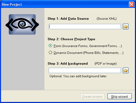
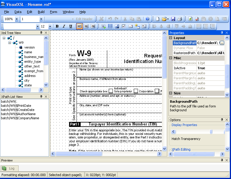
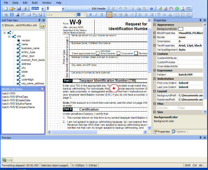
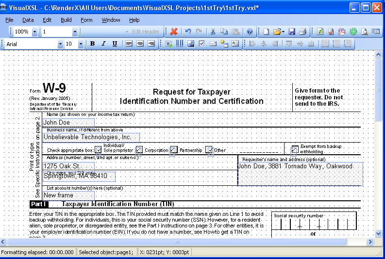
7.5. Example of Building a VisualXSL Project (ICW form)
This example assumes you are starting from an existing project. To start a new project, see Creating a New VisualXSL Project and How to Create a New Project.
The example covers the design and publishing of documents based on the ICW form from existing data in the
..\All Users\Shared Documents\VisualXSL Projects\samples\ICW folder
or
..\Users\Public\Public Documents\VisualXSL Projects\Samples\ICW folder.
A sample PDF file with a ICW form and an XML file from the database already exist. For information about preparing an XML source and PDF background, see Example of Creating XML Source and PDF Background and in Example of Exporting XML Data File from SQL Server.
Procedure 7.2. To build a Dynamic type of VisualXSL project
-
Create a new folder in
C:\Documents and Settings\All Users\Documents\VisualXSL Projects\my ICWfor the project and call it. -
Copy the
ICW.xmlandImagesfolder files from theC:\Documents and Settings\All Users\Documents\VisualXSL Projectsto the new folder. -
Open the
ICW.xmlwith an XML Editor or WordPad or Notepad with "Word Wrap" option enabled to study its content. Note the XML declarationxml version="1.0" encoding="utf-8", a good practice for it to exist, and with the correct encoding value. Note the XML elementbatchat the beginning andbatchat the end of the file. A top level XML element as noted is required by VisualXSL even if only one set of XML children elements exist. -
Open the
w9_blank.pdfwith Adobe Reader, or equivalent, to become familiar with its content and the various "blank" fields. Close and Exit Adobe Reader. -
Double-click the VisualXSL
icon on your desktop. The VisualXSL application opens.
-
Click the
button.The wizard opens.
-
Add the data source.
Under Step 1 : Add Data Source click the
button, navigate to the
..\VisualXSL Projects\Samples\ICWnew folder and select theICW.xmlfile.Note
Alternatively, you can skip the wizard, and add the data source later by using the menu to select the
ICW.xmlfile from the newly created folder.Step 2 : Choose Project Type Dynamic document(phone bills, statements)
-
Under Step 3 click the
button ,navigate to the
..\VisualXSL Projects\Samples\ICWnew folder and select theICW.xmlfile.Note that this step automatically set the and property (under ).
-
Click the button. The new project, yet unnamed, opens in VisualXSL.
-
Click , and save the project as
2ndTry.vxl. -
Click in the Layout (the Designer). The page properties are shown in the Properties pane.
-
To Create a header select
Edit header button in the tool bar.
 You can manually arrange items in the desire place on the field.
-
In the pane, find the name node, and drag-and-drop it to the Layout. Place it, and resize the name data field to fit the template in the background form.
-
Change the selected data field's properties by clicking in the pane.
-
Add Image(add rx-logo.png from
imagesfolder ),in the menu select , and in the pane, under selectImageUrl. -
Unselect .
-
Edit Items.
The Items will dynamically be arranged by turns on the layout.
-
in the or
-
To preview the project at this stage, click the button in the toolbar.
The pane helps you to monitor formatting process by tracing messages from the XEP formatter. When the XEP formatter finishes, the Preview pane shows the resulting document. You may now see how the field is placed on the page.
Caution
Click
to save the project.
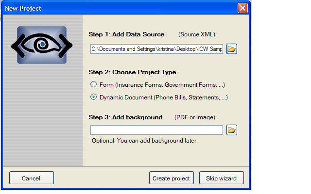
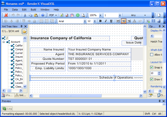
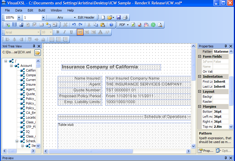
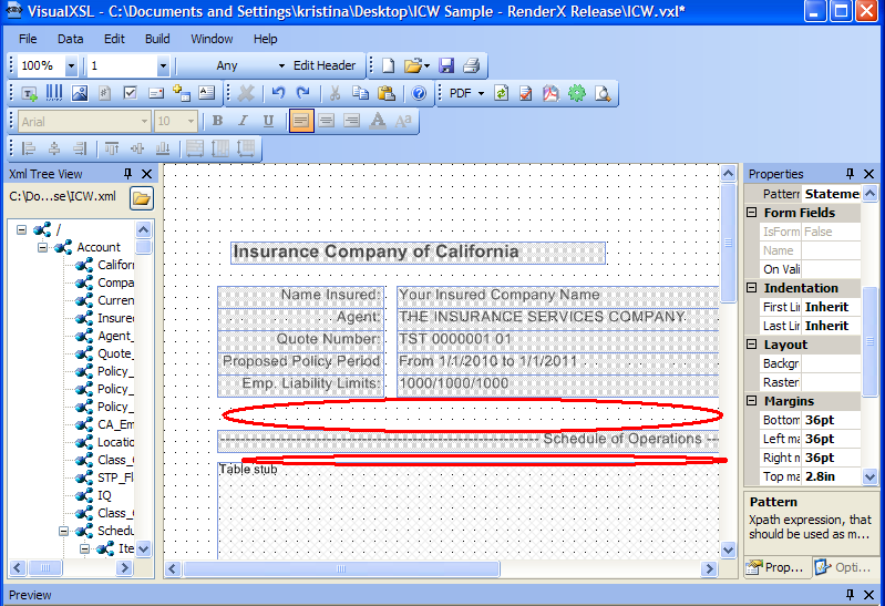
7.6. Example of Using XEP and SVG Files As Image
VisualXSL supports using both XEP intermediate format files and SVG graphics files as images. The technique is the same for both XEP intermediate format and SVG files. We illustrate using XEP file; for SVG file the scenario is similar.
Procedure 7.3. To use .XEP file as an image
-
In the
Samplefolder, open theFRUITS.pngfile. -
In the menu select Add Image, and in the pane, under Data, select ImageUrl.
-
In ImageUrl, select the
button; the following dialog box appears. -
Select Fixed Path and via Image path field browse to and select
Fruits_PNG/Images/VisualXSL/Lady_Red.xepfile. It may be necessary to change Files of type: in the file browser window, in order to show .XEP files. -
In the dialog box, click ; the dialog box closes, and the Image path in the window and the ImageUrl in the pane are set
Lady_Red.xep. -
To see the
Lady_Red.xepimage, in the menu you can click ; after completion,Lady_Red.xepis visible below in the pane.
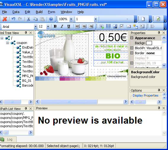
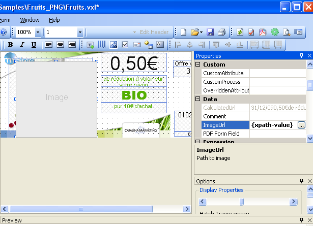
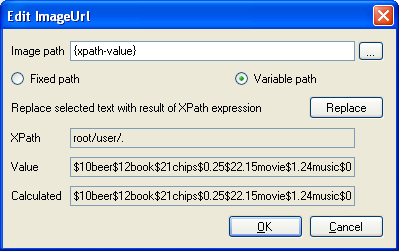

7.7. Example of Using Templates
For information about dynamic flows, see How to Create Dynamic Templates section.
In the Samples folder, open the Diners (Credit Card)
Statement file.
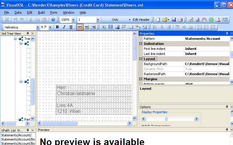
In , the template Only is shown. note the properties values, in the and property groups.
In , change from template Only to First, Last and Any, and notice that the values in the pane are changed.
For an example of how the templates work together, see the
Diners_Sample_by_RenderX.pdf file. The templates that are used for each
statement are determined by VisualXSL, according to how many
sections of data are to be presented for that statement.
7.8. Example of Using Custom Attributes
VisualXSL now supports three custom attributes properties (that is, attributes not yet natively supported by VisualXSL) for any object type. These properties (CustomAttribute, OverriddenAttribute and CustomProcess) are described in the Data Fields and Properties chapter.
The following is an example of using CustomAttribute and OverriddenAttribute:
Procedure 7.4. To use custom attributes
-
In the
Samplesfolder, open theCustomAttributesfile.Note
All of the borders of the rectangle are the same - 4pt solid cyan. We will use custom properties to access the FO style attributes for the individual border sides.
-
In the pane, under Custom, select CustomAttributes.
Change the left border to 2px red and the top border to 2px blue by entering the following value:
border-left=”solid
            2px red” border-top=”solid 2px blue”
. Note the space separating the two values. -
In the pane, under Custom, select OverriddenAttribute.
Remove the rest of the (
cyan) border altogether by entering the following value:border. -
Do either Preview or Create PDF. The updated frame's left border is red, top is blue and nothing remains of the cyan. The updated frame can be seen in the pane.
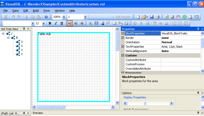
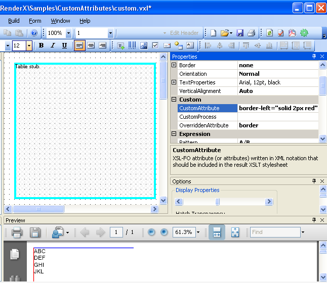
7.9. Example of Creating PDF Form
VisualXSL 2.3 and upper versions provide a new, easy to use method of creating fillable PDF Forms. Now the procedure of creating a PDF Form is the same as creating any PDF document.
This example shows how a simple PDF form can be created and submitted to the server. To submit the form, you need to have access to a server, where the data is submitted and handled.
Procedure 7.5. To create a PDF Form
-
In the
Samples/Registration Formfolder openregistration_form.vxlfile via VisualXSL. -
There are several frames, which assemble a simple registration form. The first part has a title called Registration, which contains two pairs of fields (each pair contains two fields in front each other). In this example all the pairs contain a usual text field and a fillable field (e.g. fillable text frame, checkbox, listbox, ...). Here we will pay attention to the fillable fields; more information about Text Fields can be found at 5.4 Text Frame.
-
Username - fillable text field. To create a fillable text field add a to the and set its property to true (Treat as Field is located in the section of the pane). VisualXSL sets a default value for the property, but as we need to handle the submitted data on the server, we should give names for the submitting frames. So, the name of the Username field is set to username. For all other form fields we set individual properties. We can also give the maximum allowed length of the entered text: navigate to the pane, section, property, for this field its value is 15. Besides, usually Username is a required field, to emphasis that, we gave to Required property the true value.
-
Password - password field. Password field is created from a fillable text field. To create a Password, create a fillable text field, like the Username field and set its property to true
-
The second part of the form is called Personal Data. The first two pairs are First Name and Last Name. They are created just like the Username field.
-
Then comes Gender fields, which is a group of Radio Buttons. There are used text frames and two radio buttons. Detailed information about how to create Radio Buttons see 7.3. Example of Using Radio Buttons.
-
The last pair of this section is Age. The user is suggested to select his/her age from the given intervals, which are presented as options of a . To create a select the XML node from which you wish the options to be generated and click . The values are taken from the source XML (
registration_form.xml). VisualXSL sets the current XML node's inner text as the List Box's Values. Options are generated from the Values property on the pane, its values are separated by Separator property. Here the age intervals are separated by | and as the Separator property is |, we get the desired intervals - <18, 18-20, 21-25, 26-30, 31-40, >40. -
Address section contains information about the user's address and consits of three pairs of fields.
Country - containing a list of countries. To create a select the XML node from which you wish the options to be generated and click . The values are taken from the source XML (registration_form.xml). VisualXSL sets the current XML node's inner text as the Combo Box's Values. Options are generated from the Values property on the pane, its values are separated by Separator property. Here country names are separated by | and as the Separator property is |, we get the desired intervals - Afghanistan, Albania, Algeria, etc. . -
City - Fillable Text field.
-
Address - Fillable Text field, designed for the user to write his/her address (Street, building, apartment, etc.). The only difference from other fillable fields is that it is multiline, that is - it can contain more that one line. To enable this feature set the property in the pane true.
-
The Sign section contains a and a fillable , that is a , which property is set true.
-
At the bottom of the form there are 2 - and .
Reset - this type of is used to reset all the fields to their default values. To create a Reset button, add a , in the pane set its property Reset. affects only the fields, which names are included in the property (space deliminated list); or if it is left blank, all the fields of the document are affected. As in this example property is left blank, all the fields are affected.
-
Submit - this type of is used to submit the form data to the server. To create a Submit button, add a . The server's URL is set in the property of the pane. By default it is the inner text of the XML node from which the button is created. In this example, it is
http://localhost/forms/index.php, of course you may set your own server. The submittion method is set via property, its possible values are POST and GET. Here we use POST method. VisualXSL supports four formats for submitting: XFDF, FDF, PDF and HTML. Here we used HTML format. The submitting format is changed from the property on the pane. -
After creating the form, generate the resulting PDF document, fill the form and click button. The form data will be sent to the server, which Url is given to the Submit Button's Url property. This sample includes
visualxslforms/index.phpfile, which is a simplePHPfile to show all the data sent to the server. You can copy - paste it to your php server, to see how the sample works.Note
Adobe Acrobat Reader does not read HTML format, and as in this example we use HTML to show the submitted data, you are strongly recommnded to use either window or your web browser.
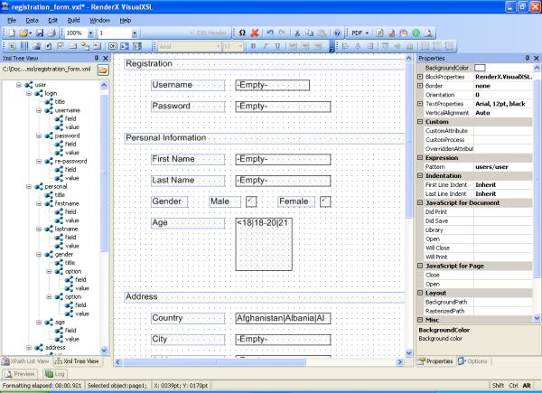
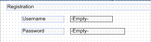
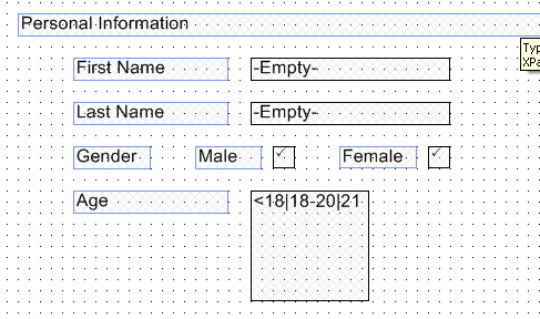
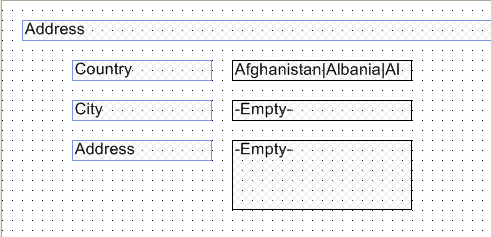
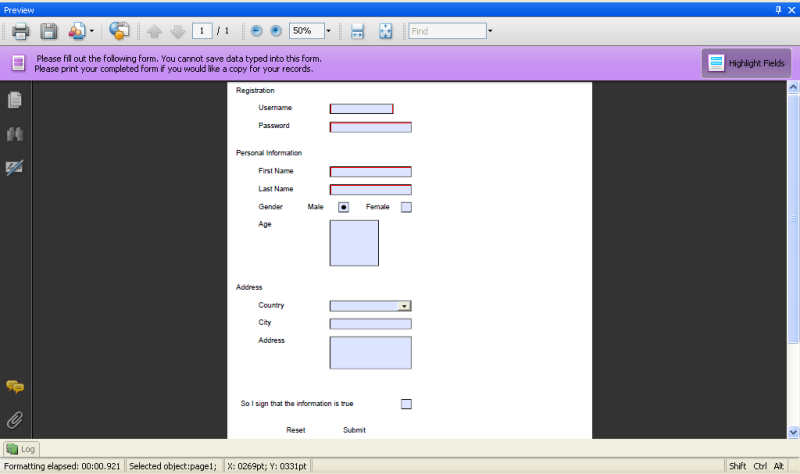
Glossary
- XEP
-
RenderX XEP is an XML to PDF (XSL FO) formatter. It takes input in XML, applies an XSL transformation to build XSL Formatting Objects representation, and then formats the Formatting Objects into PDF or PostScript. XEP supports multiple raster and vector graphic formats. Among them is Scalable Vector Graphics (SVG), an XML-based vector graphics representation that is widely used in business applications and for fine typesetting.
- XSL-FO
-
XSL-FO (XSL Formatting Objects) is an XML vocabulary for the formatting of documents. XSL-FO is part of XSL, so that the usual way to produce XSL-FO documents is by transforming XML documents using XSLT. Although the principles behind XSL and CSS (the other Style Sheet Language created by W3C) are quite different, it is planned to align the formatting model between XSL-FO and CSS, so that formatting engines can be based on the same code, both languages can be used to achieve the same results, and the formatted results will look identical.
- XSL
-
XSL (Extensible Style Language) is a Style Sheet Language that can be used for displaying XML documents. Using XSL is two-step process, the first step being a transformation of the XML document using XSLT, and the second step being the rendering of the result of the transformation, which is done using XSL-FO. XSL covers the same application area as CSS but is much more powerful, because the transformation step (using XSLT) can perform arbitrarily complex transformations of the XML document, whereas CSS is not able to make any structural changes to the XML document.
- XSLT
-
XSLT (XSL Transformations) is a specialized Programming Language for transforming XML documents. Although XSLT is part of XSL, and as such intended to be used for transforming XML documents into XSL-FO for presentation purposes, it is not limited to this application area. XSLT uses XML syntax (that is, it is a Programming Language in XML syntax), even though it is based on DSSSL (which uses a Lisp-like syntax). XSLT is particularly interesting in B2B scenarios, where XML documents must be transformed.
- .NET Framework
-
.NET Framework, created by Microsoft, is a software development platform focused on rapid application development, platform independence, and network transparency. .NET is Microsoft's strategic initiative for server and desktop development for the next decade.